


ADJUSTMENT
4.1.5 Carriage Guide Shaft Parallelism Adjustment
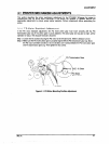
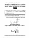
The rear carriage guide shaft must be parallel to the platen. If it is not, printing may be abnormal because
paper is not fed evenly at the left and right sides of the platen. A paper jam may occur. This adjustment is
required when the rear carriage guide shaft is removed during carriage mechanism disassembly, the
parallelism adjust lever is moved, or the platen is removed. Do not remove the printer mechanism (if remove
the printer mechanism from the lower case, the adjust value will be out of order when you reassemble the
printer mechanism to the lower case.) Also, it is necessary to remove the tension roller shaft before
performing this adjustment. (Refer to Section 326.7.)
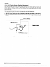
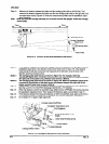
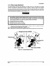
The parallelism is a#&?d so that the difference behvean the dktances (from the rear carriage guide
shaft to the platen measured at the hvo positions shown in Figure 4-5) is less man _’ 0.015 mm. Since
this value is exiramely small, you must use the two dial gauges, dia/ gauge base, and dial gauge
master supplied by EPSON. Do not adjust the parallelism using any other method
0 Dialgauges #F610 (Part No. 81019466)
0 Dialgauge base #F61 I (Part No. 81019467)
0 Dial gauge master #F612 (Part No. B1019468J.
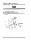
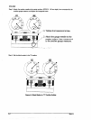
Before performing the carriage guide shaft parallelism adjustment, you must assemble the two dial gauges,
dial gauge base, and dial gauge master to form one tool. Follow these steps:
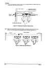
Step 1: Attach the two thumb screws for the dial gauge base to the dial gauge master. To eliminate any play
between the dial gauge base and the dial gauge master, pull the tie band to secure the dial gauge
base and the dial gauge master before you securing the thumb screws.(Do procedure with two men.)
Figure 4-5.
Set Dial Gauge to Dial Gauge Base
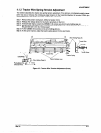
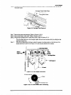
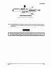
step 2: Attach a dial gauge needle to the sutface of the dial gauge master (approx. 1.00 mm depth), then
tighten the hexagonal screw securing the dial gauge to the dial gauge base.