


ADJUSTMENT
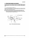
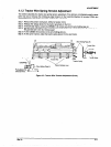
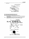
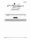
Step 6: Remove a CP(PS)(M3X6) screw securing the timing belt holder to the timing beit, then remwe the
timing belt holder.
/Carriage Guide Shaft (Rear)
Figure 4-9. Carriage Plate Removal
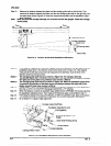
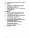
Step 7: Remove the paper bail assembly. (Refer to Section 3.2.6.5)
Step 8: Remove the tension roller shaft. (Refer to Sactiin 3.2.6.7)
Step 9: Remove the printhead with the mask-less holder. (Refer to Section 3.2.1)
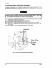
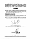
Step 10: Attach the dial gauge base with the dial gauge in the same way as you attach the print head.
Then you attach this tool to the carriage, tighten the two thumb screws while you pulling the dial
gaga base toward you.
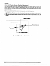
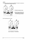
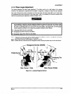
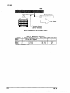
Step 11: Using the carriage guide shaft gear, adjust the gauge mounting position so that the tips of the
gauges (portions A and B in the Figure 4-10) are securely attached to the platen.
Figure 4-10. Dial Gauge Attachment
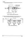
Figure 4-1Oa. CR Guide Shaft Gear Positioning
Rev. A
4-7