


DFx-6500
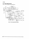
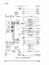
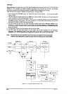
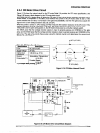
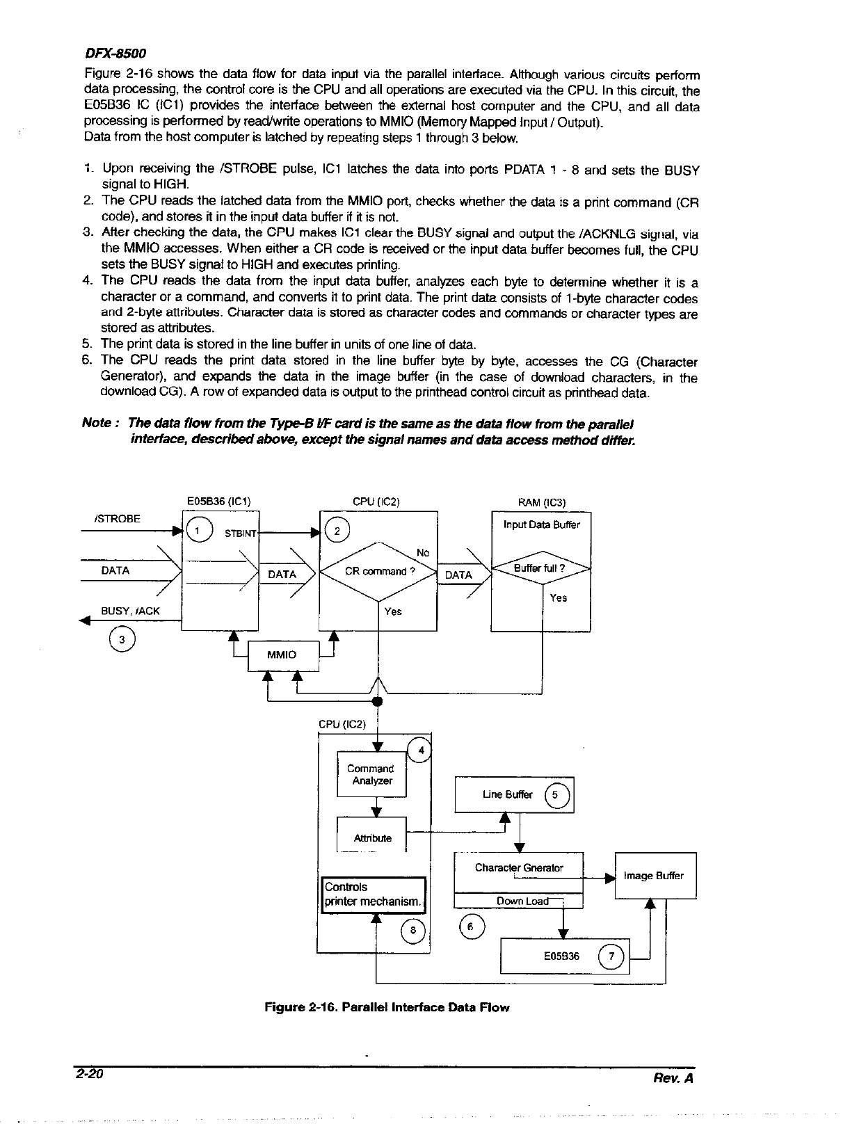
Figure 2-16 shows the data flow for data input via the parallel interface. Although various circuits perform
data processing, the control core is the CPU and all operations are executed via the CPU. In this circuit, the
E05B36 IC (ICl) provides the interface between the external host computer and the CPU, and all data
processing is performed by read/w&e operations to MM10 (Memory Mapped Input I Output).
Data from the host computer is latched by repeating steps 1 through 3 below.
1,
2.
3.
4.
5.
6.
Upon receiving the /STROBE pulse, ICl latches the data into ports PDATA 1 - 8 and sets the BUSY
signal to HIGH.
The CPU reads the latched data from the MM10 port, checks whether the data is a print command (CR
code). and stores it in the input data buffer if it is not.
After checking the data, the CPU makes ICl clear the BUSY signal and output the /ACKNLG signal, via
the MM10 accesses. When either a CR code is received or the input data buffer becomes full, the CPU
sets the BUSY signal to HIGH and executes printing.
The CPU reads the data from the input data buffer, analyzes each byte to determine whether it is a
character or a command, and converts it to print data. The print data consists of l-byte character codes
and 2-byte attributes. Character data is stored as character codes and commands or character types are
stored as attributes.
The print data is stored in the line buffer in units of one line of data.
The CPU reads the print data stored in the line buffer byte by byte, accesses the CG (Character
Generator), and expands the data in the image buffer (in the case of download characters, in the
download CG). A row of expanded data is output to the printhead control circuit as printhead data.
Note :
The data flow from the Type-B UF card is the safne as the data flow from the parallel
interface, described above, except the signat names and data access method differ
Figure 2-16. Parallel Interface Data Flow
2-20
Rev. A