


DISASSEMBLY AND ASSEMBLY
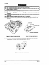
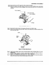
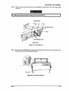
Step 5: Disconnect the narrow FPC cable from white connector (lock-type).
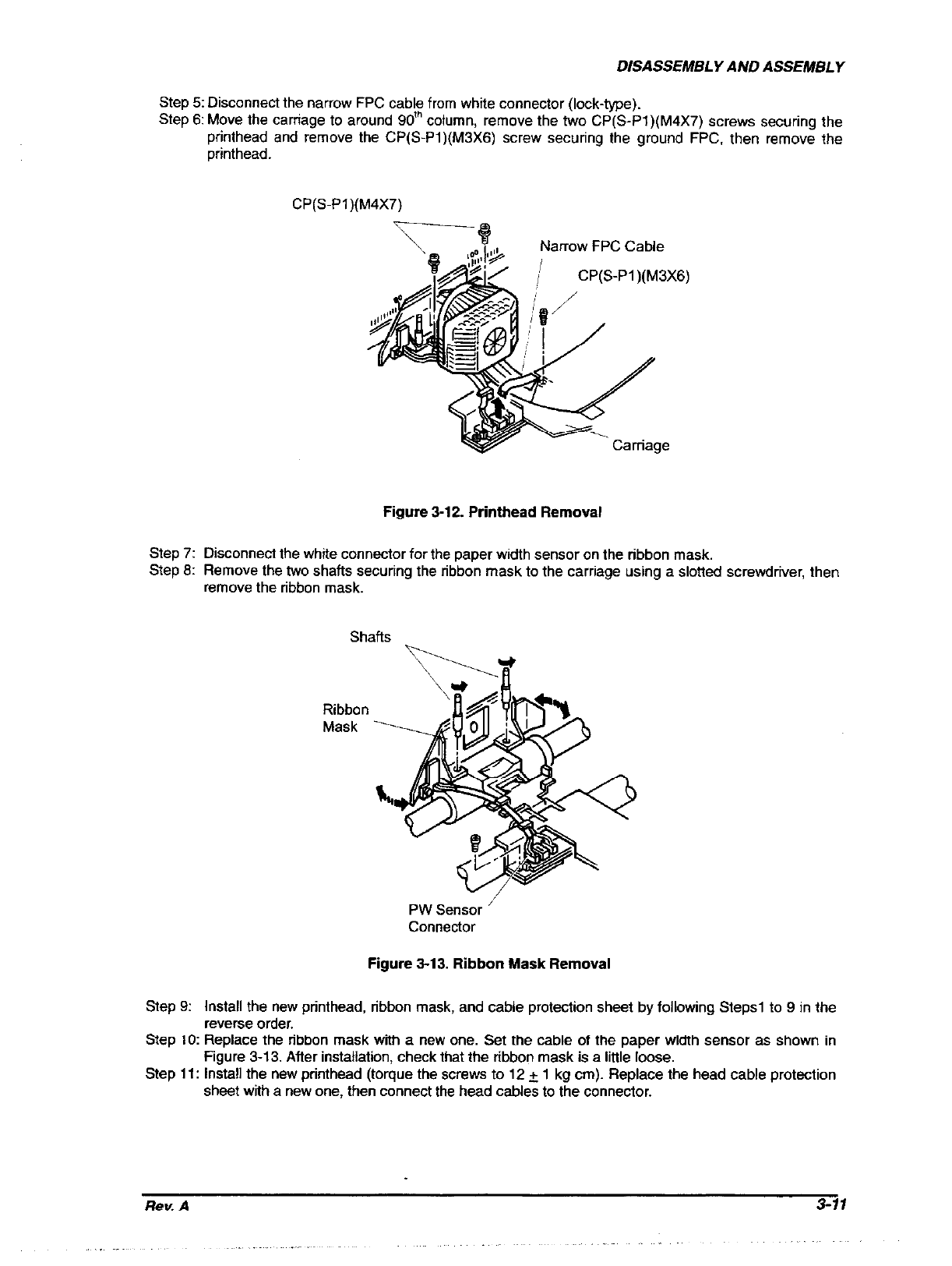
Step 6: Move the cartiage to around 90’” column, remove the two CP(S-Pl)(M4X7) screws securing the
printhead and remove the CP(S-Pi)(M3X6) screw securing the ground FPC. then remove the
printhead.
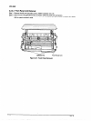
CP(S-Pl)(M4X7)
Narrow FPC Cable
CP(S-Pl)(M3X6)
Figure 3-12. Printhead Removal
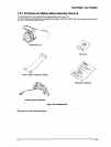
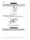
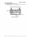
Step 7:
Disconnect the white connector for the paper width sensor on the ribbon mask.
Step 6: Remove the two shafts securing the ribbon mask to the carriage using a slotted screwdriver, then
remove the ribbon mask.
Ribbon
Mask
PW sensor ’
Connector
Figure 313. Ribbon Mask Removal
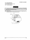
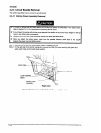
Step 9:
Install the new printhead, ribbon mask, and cable protection sheet by following Steps1 to 9 in the
reverse order.
Step 10: Replace the ribbon mask with a new one. Set the cable of the paper width sensor as shown in
Figure 3-13. After installation, check that the ribbon mask is a little loose.
Step 11: Install the new printhead (torque the screw to 12 + 1 kg cm). Replace the head cable protection
sheet with a new one, then connect the head cables to the connector.
Rev. A
3-11