


DISASSEMBLY AND ASSEMBLY
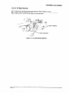
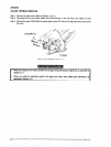
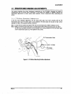
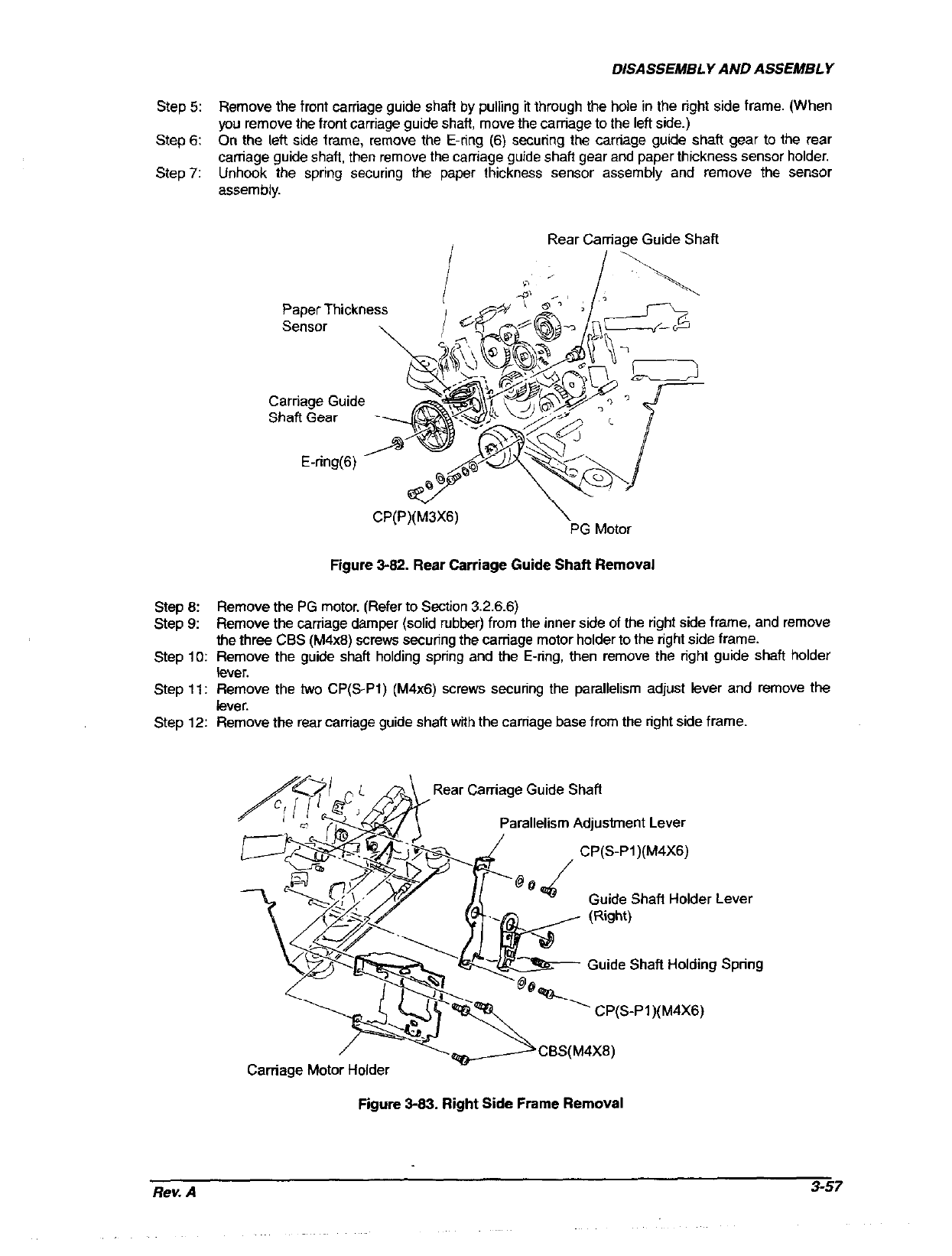
Remove the front carriage guide shaft by pulling it through the hole in the right side frame. (When
you remove the front carriage guide shaft move the carriage to the left side.)
On the left side frame, remove the E-ring (6) securing the carriage guide shaft gear to the rear
carriage guide shaft, then remove the carriage guide shaft gear and paper thickness sensor holder.
Unhook the spring securing the paper thickness sensor assembly and remove the sensor
assembly.
Step 5:
Step 6:
Step 7:
Step 6:
Step 9:
Step 10:
step 11:
Step 1.2:
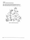
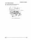
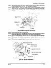
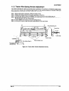
Rear Carriage Guide Shaft
Paper Thickness
Sensor 1
CP(P)(M3X6)
\
PG Motor
Figure 3-62. Rear Carriage Guide Shafl Removal
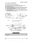
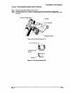
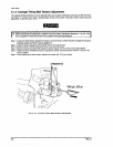
Remove the PG motor. (Refer to Section 3.2.6.6)
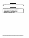
Remove the carriage damper (solid rubber) from the inner side of the right side frame, and remove
the three CBS (M4x8) screws securing the carriage motor holder to the right side frame.
Remove the guide shaft holding spring and the E-ring, then remove the right guide shaft holder
fever.
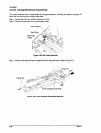
Remove the two CP(S-Pl) (M4x6) screws securing the parallelism adjust lever and remove the
lever.
Remove the rear carriage guide shaft with the carriage base from the right side frame.
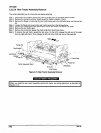
Rear Carriage Guide Shaft
Parallelism Adjusbnent Lever
CP(S-Pi)(M4X6)
/
@Qfi
Guide Shafl Holder Lever
Guide Shaft Holding Spring
Carriage Motor Holder
Figure 3-83. Right Side Frame Removal
Rev. A
3-57