


DISASSEMBLY AND ASSEMBLY
3.2.6 Printer Mechanism Removal
This section describes how to remove and disassemble the printer mechanism. Before following the steps in
this section, remove the printer mechanism from the printer as described in Section 3.2.6.
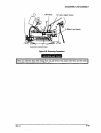
Because the printer mechanism is large and heavy, you must be careful when you remove it. When yor,
lift or lower the printer mechanism, follow these precautions:
0 Two people are required to remove or install the printer mechanism.
0 Use the fift handles (#E656, part number t3765111001) designed for Ming or lowering the printer
mechanism when you remove or install it.
0 To avoid straining your waist, hands, or feet, place the printer on a low tab/e before following the
steps below.
Step 1: Remove the upper case (Refer to Section 323.4.).
Step 2: Remove the interlock switch assembly (Refer to Section 3.25).
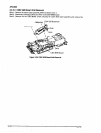
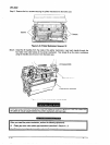
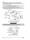
Step 3: Remove the two CBS (0) (M4x8) screws securing the green and yellow earth cables to the
grounding plate. Then disconnect connectors (1) through (4) as shown in Figure 3-42. (Ensure all
connectors (1) through (7) indicated in the figure are disconnected.)
Step 4: Remove the CBS (0) (M4x8) screw securing the earth cable as shown in Figure 3-42.
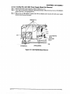
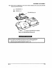
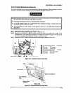
0 Flat Cable Connector (W-pin):
Mechanism
0 CN4 (Cpin): CR Connector
0 CN9 (,-pin):
optnn cutter
0 Flat Cable Connector (50-pin):
Printhead
0 l”k?dc& suit* cable (*-pi”)
0 CN3 (Spin): cover Open sensor
@ CN5 (1Cpin):
Panel Unit
Figure 3-41. Connector Removal (left side)
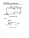
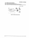
Earth Cable
S(0) Screw(M4x8)
C204 PSB/PSE
Board
Bottom Panel
Assembly
(Right side)
Figure 3-4?. Connector Removal (right side)
Rev. A
3-29