


DISASSEMBLY AND ASSEMBLY
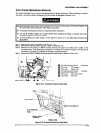
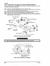
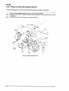
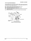
3.2.6.6 PG Sensor and PG Motor Removal
When you remove or install the PG sensor, be careful not to bend the PG motor detection boa&.
I]
Step 1: Remove the connector junction board assembly. (Refer to Section 3.265)
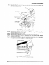
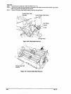
Step 2: Remove the CBS screw (3X6) securing the PG sensor unit to the left frame. Then take out the
unit to the front and remove it.
Step 3: Remove the screw securing the PG sensor to the unit, and remove the sensor.
Step 4: Remove two CP (S-PI) (M3x6) screws securing the PG motor and remove the motor.
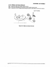
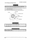
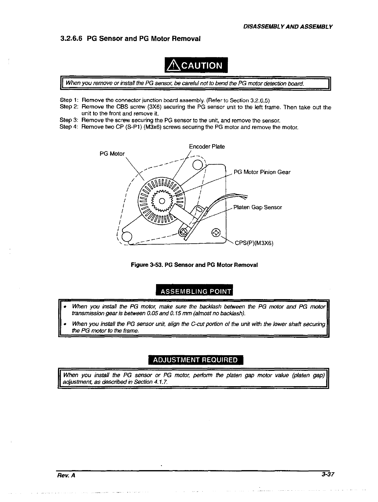
PG Motor
Encoder Plate
L-.
PG Motor Pinion Gear
Figure 3-53. PG Sensor and PG Motor Removal
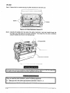
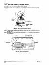
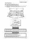
l When you install the PG motor, make sure the backlash between the PG motor and PG motor
transmission gear is between 0.05 and 0.15 mm (almost no backlash).
. When you install the PG sensor unit, a/;gn the C-cut portion of the unit with tha lower shaft securing
the PG motor to the frame.
When you instaII the PG sensor or PG motor petform the p/aren gap motor val0.a (platen gap)
adiustment. as described in Sectfon 4.1.7.
Rev. A
3-37