


OPERATING PRINCIPLES
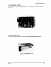
2.1.2 Carriage Mechanism
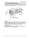
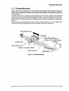
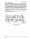
Figure 2-5 shows the carriage mechanism. The front and rear carriage guide shafts support the carriage. The
rotation of the CR motor is transmitted to the carriage timing belt through the carriage belt pulleys at the right
and left sides. The printhead is mounted on the carriage, which is attached to the carriage timing bek and
moves horizontally.
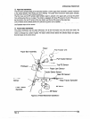
The printer does not have a carriage home position sensor; the home position is detected using disordered
pulses of the CR motor and CR encoder sensor (linear, bek-type). A gum pad is attached to the left side of
the frame. When the carriage hits the pad, the CR motor pulse is disordered by this obstacle. The control
circuit monitors the CR motor’s pulse; when it is disordered, the control circuit recognizes the carriage home
position.
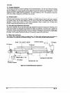
The encoder belt has equally pitched slits and is mounted under the timing belt. A photo interrupter (CR
encoder) surrounds the encoder belt and converts the carriage movement into a pulse train.
Head Dumper (Left) _
Encoder Sensor
4r aelr
!_ Printhead
:’
\‘A., R
Ribbon Mask Holder
Z-Paper Thickness Sensor
/SHAFT, CR, GUIDE, REAR
- TIMING BELT, CR
Figure 2-5. Carriage Mechanism
Rev. A
2-5