


OPERATING PRINCIPLES
0 PI Control :
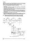
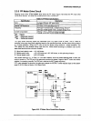
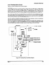
PI control keeps the CR motor speed constant using the encoder pulses ENCA and ENCB with the gate
array EO5B36. The E05B36 generates the PWM (pulse width modulation) signal according to the CR motor
speed to the PWM port of the gate array and detenines the duty of the carriage driie timing.CR ports IO, II,
and I2 output the drive signal for the CR motor.
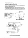
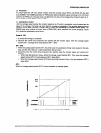
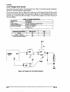
0 Acceleration control :
Until the carriage speed reaches the constant speed set by PI control, acceleration control determines the
speed of the carriage. The printer can print while the carriage is accelerating. The carriage speed moves to
constant control speed smoothly to prevent the CR motor from exceeding the constant control speed. The
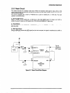
EOSB36 gate array controls the motor driver (STK681-050), which performs the current chopping. Figure
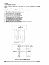
2-21 shows the acceleration control cwve.
speedo-SP1
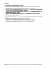
1. It causes the carriage to accelerate.
2. Because the control circuit measures time periods with the encoder signal, when the carriage speed
reaches SPl, ii changes to the next sequence (SPl - SP2).
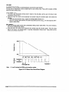
SPl - SPZ
1. When the carriage speed reaches SPl , the printer uses the acceleration driving mode, based on the duty
data, and the rest of the time, it uses Deceleration driving mode 2.
2. During this time the control circuit measures time periods using the encoder signal, and controls the
followi”g:
l When duty data becomes Dutyti before the carriage speed reaches SP2. Then, when the caniage
speed reaches SP2, the next sequence (SP2-) takes effect.
l When the carriage speed reaches SP2 before duty data becomes Duty,,, the next sequence (SPZ-)
takes effect.
SP2-
When the carriage speed reaches SP2, PI control oversees the cardage speed.
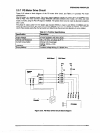
Figure 2-21. CR Motor Drive Circuit Block Diagram