


DFX-&700
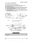
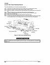
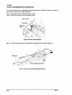
3.2.6.18 Rear Tractor Assembly Removal
This section describes how to remove the rear tractor assembly.
Step 1: Disconnect the connector white 3-pin rear PE sensor from the connector junction board.
Step 2: Remove the connector junction board assembly. (Refer to Section 326.5)
Step 3: Remove the flange nut securing the wire holder spring set to the right side frame, and remove the
set.
Step 4: Loosen the flange nut securing the rear tractor assembly to the left side frame.
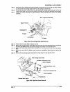
Step 5: Remove the CBS(M4x8) screw securing the tractor wire holder and remove the holder.
Step 6: Remove the rear tractor gear.
Step 7: Remove the E-ring and release the shaft holder from the left side frame.
Step 6: To remove the rear tractor assembly, first move it to the left to releasa the right end of the shaft
from the right side frame. Then release the left end of the shaft and remove the assembly.
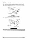
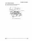
Tractor Wire Holder
Shaft Holder
Figure 3-75. Rear Tractor Assembly Removal
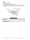
When you install the rear tractor assembly, psffum the tractor wire spring @ustmenr, as desctibsd in
section 4.7.3.
3-52
Rev. A