


OPERATING PRINCIPLES
2.3.4 CR Motor Drive Circuit
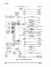
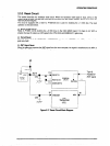
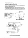
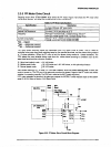
Figure 2-19 shows the internal circuit for the CR motor,Table 2-6 provides the CR motor specification, and
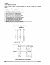
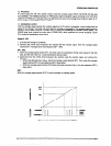
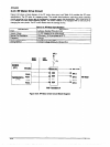
Figure Z-20 shows a block diagram for the CR motor drive circuit.
An STKMl-050 (ICl) bipolar driver IC drives the CR motor. It has buiit-in bipolar switching transistors and a
current limiter. A comparator IC uPC393C (IC3) monitors the current in the CR motor driver IC (ICl). If the
current exceeds the set value, it is fed beck to the gate array (E05B36), and then the gate array outputs the
signal for the current setting transistors (05, Q6, and Q7).
When the printer is turned on, CPU analog pod AN2 measures the isolation resistance in the CR motor. If the
isolation resistance is equal or less than 2.2 K ohms, the printer change the status to the carriage error.
If the printer cover is open during power on, the CR motor driver power is cut by the interlock switch.
The ENCA pulse that the carriage encoder outputs is input to general purpose port CRENCA of the gate
array, and the ENCB pulse that the carriage encoder outputs is input to general purpose polt CRENCB of the
gate array. The gate array counts these pulses using the internal counter and determines the amount and
direction of motor rotation.
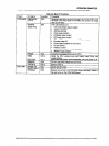
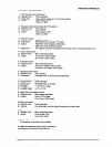
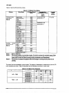
Table 26. CR Motor Specifications
Speciiication
Description
Fon
DC servo motor
Supply VoRage 37 VDC
Internal Coil
1.66 ohms (+ 10 %)
-1
l l): at Super draft printing, + 10 %
Figure 2-19. CR Motor Internal Circuit
Figure 2-20. CR Motor Drive Circuit Black Diagram
Rev. A
2-25