


DISASSEMBLY AND ASSEMBLY
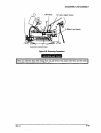
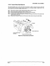
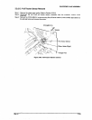
3.2.6.9 Tension Roller Shaft Removal
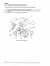
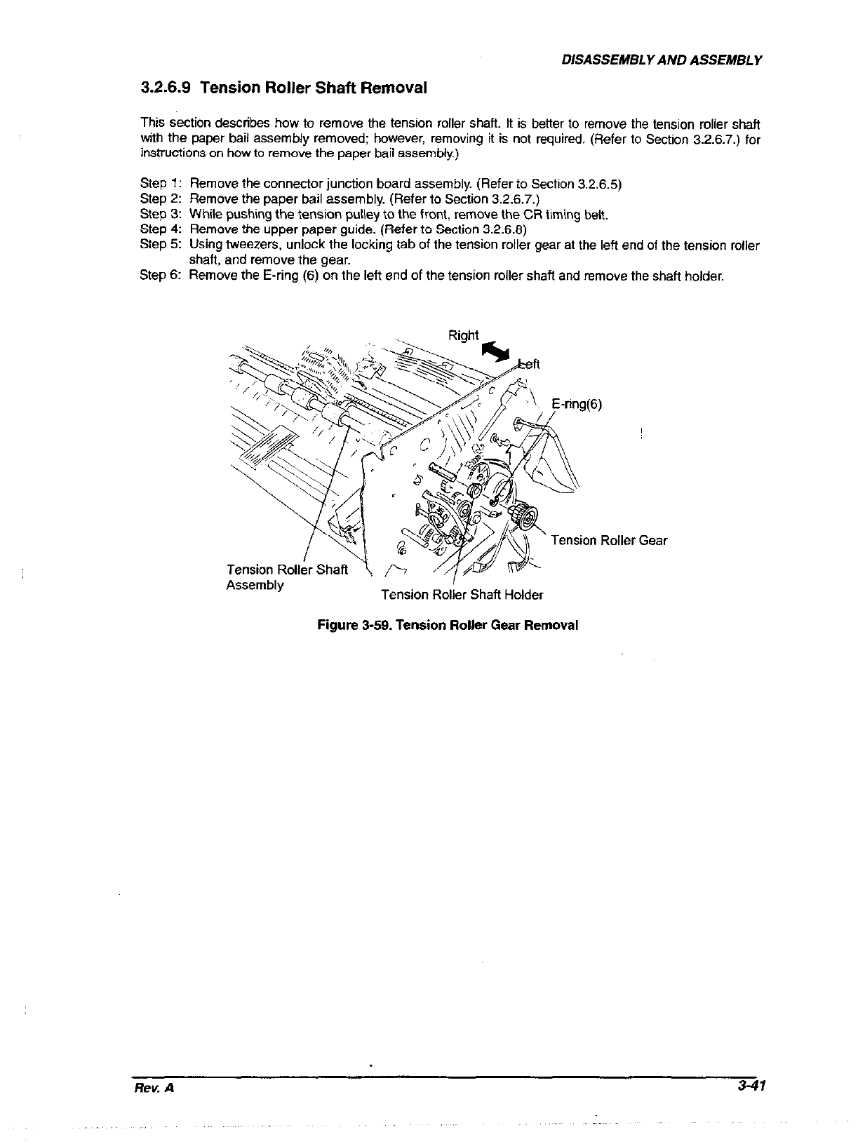
This section describes how to remove the tension roller shaft. It is better to remove the tension roller shaft
with the paper bail assembly removed; however, removing it is not required. (Refer to Section 326.7.) for
instructions on how to remove the paper bail assembly.)
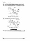
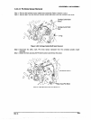
Step 1: Remove the connector junction board assembly. (Refer to Section 3.2.6.5)
Step 2: Remove the paper bail assembly. (Refer to Section 3.2.6.7.)
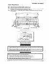
Step 3: While pushing the tension pulley to the front, remove the CR timing belt.
Step 4: Remove the upper paper guide. (Refer to Section 3.2.6.8)
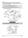
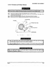
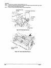
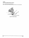
Step 5: Using tweezers, unlock the locking tab of the tension roller gear at the left end of the tension roller
shaft, and remove the gear.
Step 6: Remove the E-ring (6) on the left end of the tension roller shaft and remove the shaft holder.
Tension Roller Gear
Assembly
I
Tension Roller Shaft Holder
Figure 3-59. Tension Roller Gear Removal
Rev. A
3-47