


TROUSLESHOOTlNG
5.2 CIRCUIT BOARD REPAIR
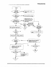
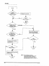
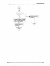
This section provides detailed troubleshooting methods to isolate components in the power supply or on the
main board. This information is for use by service personnel who repair to the component level.
The table below provides causes, checkpoints, and solutions for different power supply circuit problems. The
checkpoints include waveforms for normal operation. By referring to the checkpoints, determine the defective
component. Then perform the proper repair. The table provides the following four columns:
0 Symptom: Check this column for a list of common printer problems.
D Cause:
Use this column to identify possible causes that could produce this symptom.
0 Checkpoint:
Follow the troubleshooting checks in this column to isolate your problem.<
0 Solution:
Repair the printer using the instructions in this column.
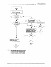
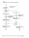
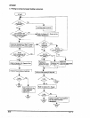
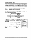
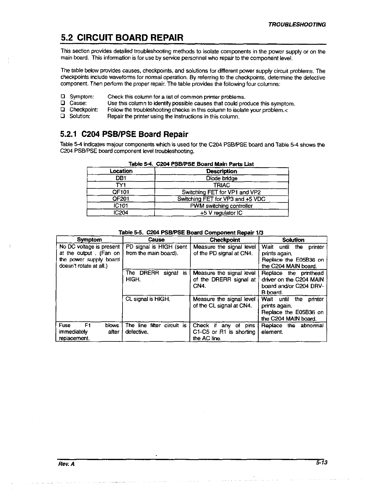
5.2.1 C204 PSB/PSE Board Repair
TaMe 5-4 indicates majour components whiih is used for the C204 PSBiPSE board and Table 5-4 shows the
C204 PSBIPSE board component level troubleshooting.
Table 5-4. C204 PSBlPSE Board Main Parts List
Location
Description
DBl
Diode bridge
TYl
TRIAC
QFlOl
Switching FET for VP1 and VP2
QF201
Switching FET for VP3 and +5 VDC
IClOl PWM switching controller
IC204 +5 V regulator IC
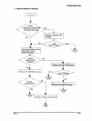
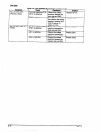
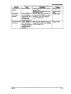
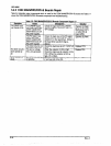
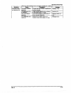
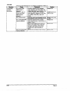
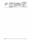
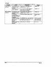
Table 5-5. C204 PSB/PSE I
Symptom
I
Cause
No DC voltage is present PD signal is HIGH (sent
at the output (Fan on from the main board).
the wwer suoohr board I
doe&t mtate ai all.)
IYKxK%x
) HIGH. -
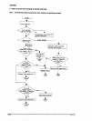
CL signal is HIGH.
Fuse Fl
immediately
replacement.
blows The line fitter circuit is
after defective.
3c
lard Component Repair 113
Checkpoint Solution
Measure the signal level Wait until the printer
of the PD signal at CN4.
prints again.
Replace the E05B36 on
the C204 MAIN board.
Measure the signal level Replace the printhead
of the DRERR signal at driver on the C204 MAIN
CN4.
board an&or C204 DRV-
B board.
Measure the signal level Wait until the printer
of the CL signal at CN4. prints again.
Replace the E05B36 on