


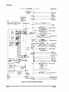
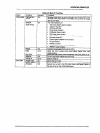
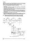
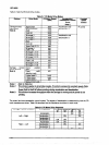
Each sensor is described below.
1.
Cl
0
0
2.
cl
cl
P
Front and rear paper end sensors
Detection fon: Photo interrupter
output form:
Open collector (pulled up to 10 K ohms resistor)
Logical:
Paper present: LOW
Paper out: HIGH
TOD oaoer end sensor (to detect the TOF position)
D&iion fon:
output form:
Logical:
Photo reflector
Open collector
Paper present: LOW
Paper out: HIGH
3. Paper jam sensor
cl Detection form:
0 Outputform:
0 Logical:
0 Supplement:
4. Tractor select sensor
0 Detection form:
0 Logical :
Micro mechanical switch
Front tractor: LOW (closed)
Rear tractor: HIGH (open)
5. Pull tractor sensor
0 Detection form:
0 Logical:
Magnetic transistor
Rectangle wave (1 channel, lTL level)
Paper feed: Level changes continuously,
Paper jam: Level remains the same.
The magnetic transistor is attached to the tension roller on the paper tension unit
Micro mechanical switch
Pull tractor installed: LOW (closed)
Pull tractor not installed: HIGH (open)
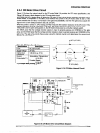
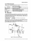
6. Carriage encoder sensor
0 Detection form: Photo reflector
0 Transaction:
Rectangle wave, A and B phases respectively.
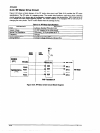
7. Platen Gap encoder sensor
0 Detection form: Photo interrupter
Cl Output form:
Rectangle wave, 2 channel
P PGabilii: T = 0.015 mm I puls6
0 Available range: O~T~0.7mm
8. Platen Gao home oostion sensor
0 Detection’ form:
Cl Logical::
Micro mechanical switch
Home: LOW (closed)
Out of home: HIGH (open)
9. Ribbon jam sensor
0 Detection form:
0 Function: :
Photo interrupter
The main board monitors signal change during ribbon feed,
10. cover open sensor
0 Detection foml: Micro mechanical switch
P Logical:: Cover closed: LOW
Cover open: HIGH
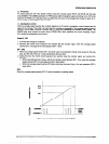
11. Printhead temperature sensor (uses a thermistor)
The therm&or is included on the printhead.
12. Head fan temperature sensor (uses a thermistor)
The thermostor is included on the head fan.
Rev. A
2-23