


7-29
Capture and Display Filters
Filter Examples
7
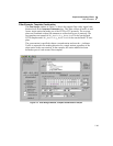
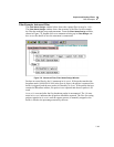
Filter Example, Advanced Filter
The
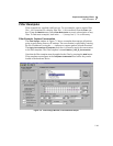
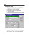
Filter States Design window below shows the capture filter Example.CFD.
The
Filter States Design window shows the structure of the filter. In the example,
the filter has multiple states and statements. From the
Filter States Design window,
shown in Figure 7-8, double-click on a statement to bring up its
Filter Design win-
dow to see the details of how the statement is constructed.
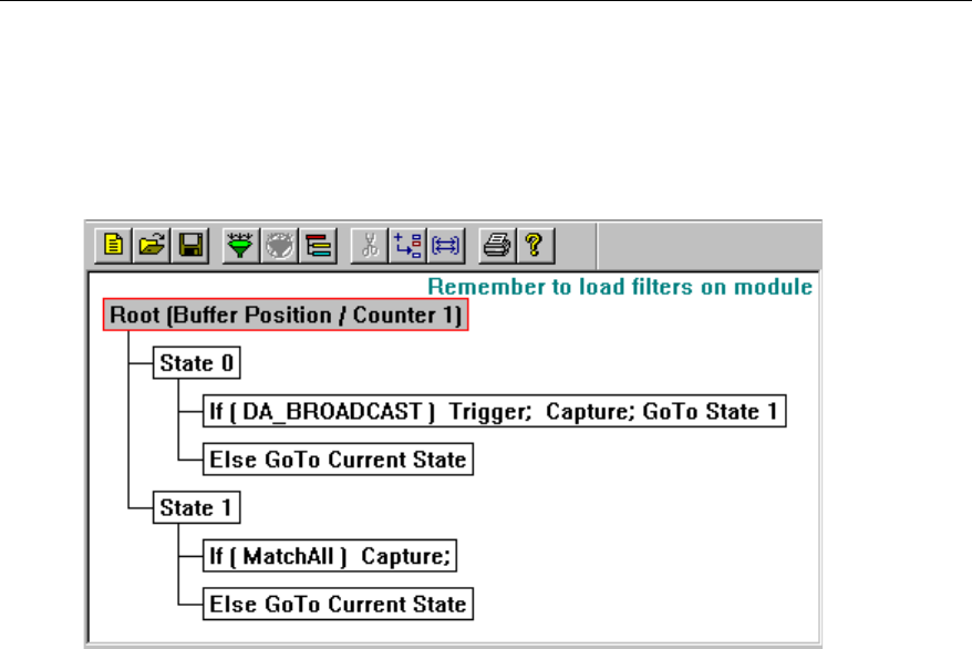
Figure 7-8. Advanced Filter, Filter States Design Window
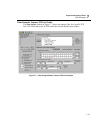
Packets are tested first by the IF statement in State0. If the packet matches the
broadcast mask (FFFFFFFFFFFF in the first six bytes), the packet is captured, the
buffer is triggered, and the next packet is filtered by State1. If the packet does not
contain the Broadcast address, the packet is not captured and the next packet is fil-
tered.
State1 is executed after the first broadcast packet is encountered. The IF state-
ment in State1 indicates that all packets should be captured. The flow for testing
packets remains in State1 until the capture process is manually stopped or the
buffer is filled to the percentage entered by the user.