10-6
Surveyor
User’s Guide
Expert Layers
Surveyor categorizes network problems according to the network “layer” at which
they occur. During capture or monitor, Surveyor decodes frames. The decode
information embedded in each frame is used to categorize the problem.
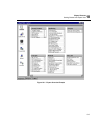
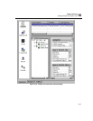
Layers are selected from the panel on the left of the Expert window. A display of
symptoms can be refined by pressing one of the layer icons in the display.
The categories used by the Expert system are shown below. The categories
correspond roughly to the OSI protocol layer model for communications.
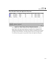
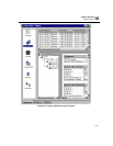
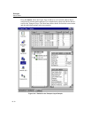
Figure 10-3 shows an example Expert Application Layer window for symptoms.
The summary area (top) lists all symptoms for the selected layer. The detail area
(bottom left) shows an object tree view of the symptom selected in the summary
area. This provides information about the stations, ports, and their relationships that
are associated with the selected symptom. The vital statistics for the symptom
selected in the summary area are shown in the detail area to the right. The first table
shows other symptoms discovered for this conversation. Detailed statistics for each
entity in the conversation and statistics for the conversation itself are also included.
The summary and detail areas are separated by large gray bars (one vertical and one
horizontal) which can be used to size each area as needed.
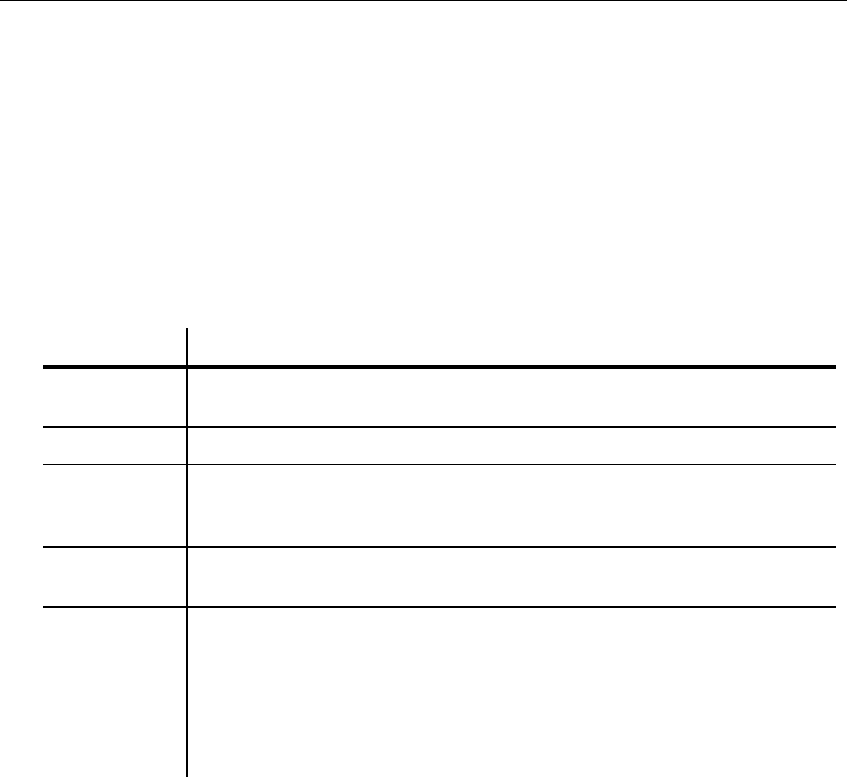
Layer Description
Application Surveyor checks for application problems. These are generally servers running
protocols with a client-server relationship, such as HTTP or FTP.
Session Surveyor checks for problems related to administration and security.
Transport Surveyor checks for problems related to the efficiency of end-to-end communi-
cations and error recovery. This layer essentially logs connection-related prob-
lems.
Network Surveyor checks for network addressing and routing problems. It also inter-
prets traffic between subnets.
Data Link Surveyor logs symptoms/problems with the actual transfer of data across the
network. For example, it keeps track of the number of broadcast frames and
the number of bytes transmitted during a predefined interval to detect network
overload.
Physical errors such as CRC errors and frames that are too short are also
detected. The software does not perform diagnoses on the physical character-
istics of the network such as electrical voltage and current.


