


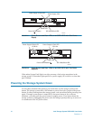
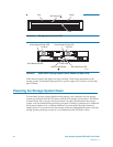
Intel Storage System SSR212PP User Guide 93
PRELIMINARY
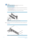
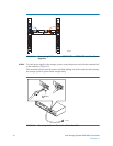
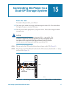
STEP 3. For each power supply in the storage system, plug the storage system power cord into the
AC power source in the cabinet (power distribution unit) or other source (Figure 37 or
Figure 38).
The power supply on light turns on indicating that the power supply is connected to an
active AC power source.
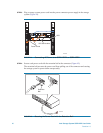
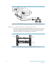
STEP 4. If the storage system will be connected to the server through a switch, plug one end of
the switch power cord to the power connector on the switch and the other end into an AC
power source, as described in the documentation that shipped with the switch.
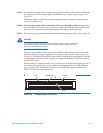
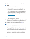
STEP 5. Press the storage system power on/off button to initiate powerup (Figure 40 or Figure 41).
CAUTION
Press the power button only briefly to power up the storage system. Pressing the
power button for more than four seconds while the storage system powers up
may affect initialization parameters.
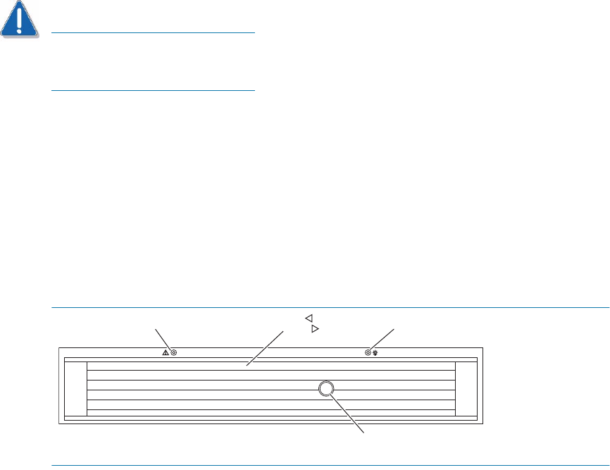
The green power lights (LEDs) on the front and back of the storage system turn on and
remain on as long as power is applied to the storage system (Figure 40 and Figure 41 or
Figure 42). The amber SP Boot/Fault light flashes to indicate powerup progress. The Disk
Activity lights on the front of the storage system light intermittently as the disks spin up
and disk I/O begins.
When powerup is complete (usually in 5 to 6 minutes), the SP Boot/Fault light goes off. If
the storage system does not power up within several minutes and/or the fault indicator
goes on, refer to the "Troubleshoot" section on the SSR212PP support website or the
SSR212PP-Series Documentation CD.
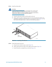
FIGURE 40. Storage System Front LEDs
Fault
Disk Activity
SAB2934
Power
Lock