38 Intel Storage System SSR212PP User Guide
Revision 1.0
PRELIMINARY
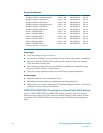
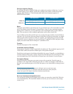
Sample IP addresses
Port IP address Subnet mask Gateway
Storage Processor A management port 172.31.1.200 255.255.255.0 0.0.0.0
Storage Processor A iSCSI port 0 172.31.1.150 255.255.255.0 0.0.0.0
Storage Processor A iSCSI port 1 172.31.2.150 255.255.255.0 0.0.0.0
Storage Processor B management port 172.31.1.201 255.255.255.0 0.0.0.0
Storage Processor B iSCSI port 0 172.31.1.151 255.255.255.0 0.0.0.0
Storage Processor B iSCSI port 1 172.31.2.151 255.255.255.0 0.0.0.0
Server 1 iSCSI NIC/HBA 1 172.31.1.101 255.255.255.0 0.0.0.0
Server 1 iSCSI NIC/HBA 2 172.31.2.101 255.255.255.0 0.0.0.0
Server 2 iSCSI NIC/HBA 1 172.31.1.102 255.255.255.0 0.0.0.0
Server 2 iSCSI NIC/HBA 2 172.31.2.102 255.255.255.0 0.0.0.0
Server 3 iSCSI NIC/HBA 1 172.31.1.103 255.255.255.0 0.0.0.0
Server 3 iSCSI NIC/HBA 2 172.31.2.103 255.255.255.0 0.0.0.0
Continue for up to 10 servers . . .
Advantages
Low-cost storage for up to ten servers.
Connection to multiple servers maximizes the use of the storage system s capabilities.
The use of dedicated iSCSI LANs avoids network contention with your corporate
LAN and reduces security risk.
This configuration offers the best overall failover capabilities to withstand storage
processor, switch, initiator, or cable failures.
Using two storage processors improves overall storage system performance.
Disadvantages
Duplicate hardware raises configuration costs.
Redundancy increases hardware configuration and setup complexity.
Reduced access for remote management: To perform management tasks, you must be
connected to a host on the private network.
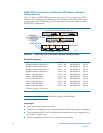
SSR212PP2i/SSR212PPi Connected to a Shared Public/iSCSI Network
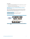
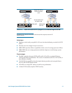
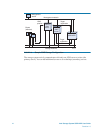
Figure 18 shows SSR212PP2i and SSR212PPi storage systems with up to ten servers.
Each server has a single iSCSI NIC connected with an Ethernet switch (shared for both
corporate LAN and iSCSI traffic) to the storage system s iSCSI data and management
ports.


