114 Intel Storage System SSR212PP User Guide
Revision 1.0
PRELIMINARY
For dual-SP systems, connect either FE port on SP A to one switch and either FE
port on SP B to another switch port.
Customer-installable switches are easily configured, and some are preconfigured,
to use ports 0 and 4 only for SP connections and ports 1-3 and 5-15 only for HBA
connections. With switches set up in such "hard zones," you can connect FE 0 or
FE 1 to ports 0 and 4 only, and connect HBAs only to ports 1—3 and 5—15.
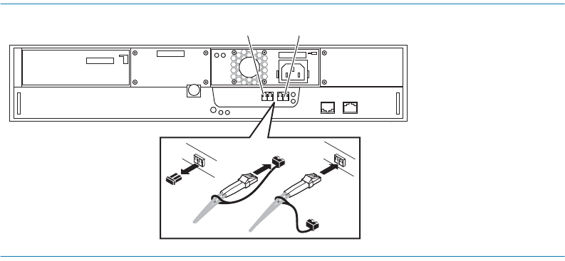
STEP 1. For each FE port that you want to connect to an HBA connector.
a. Remove the protective covers from the FE connector on the SP and from one end of
the optical cable, and plug the cable into the FE connector.
b. Remove the protective covers from the optical connector on the HBA and from the
free end of the optical cable and plug the cable into the HBA connector (Figure 54 or
Figure 55).
STEP 2. For each FE port that you want to connect to the switch:
a. Remove the protective cover from the optical connector on the switch port that you
will use and from one end of the optical cable, and plug the cable into the switch port
(Figure 54 or Figure 55).
b. Remove the protective covers from the FE connector on the SP and from the free end
of the optical cable, and plug the cable into the FE connector (Figure 54 or Figure 55).
FIGURE 54. SSR212PPf Front End (FE) and Optical Cable Connectors
FE 1FE 0
FE 0
FE 1
EMC3281


