


2-40 Service Manual
5016-001
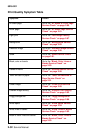
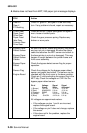
FRU Action
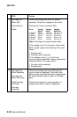
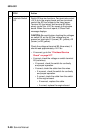
1 Carriage Unit
Motor (M3)
Engine Board
Cable
Check the carriage unit motor for proper
operation. Check the voltages on the motor.
Carriage unit motor connector (M3).
Pin # Voltage Voltage Voltage
Signal Static Motor On
1 (Yellow) PH1B- +24 V dc 20 - 24 V dc
2 (Red) +24 V dc +24 V dc +24 V dc
3 (White) PH1B+ +24 V dc 20-24 V dc
4 (Brown) PH1A+ +24V dc 20-24 V dc
5 (Violet) PH1A- +24V dc 20-24 V dc
Note: All voltages are approximate values.
If the voltage on pin 2 is incorrect, check cable
MK2. If good, replace the following in the order
shown:
1. Engine board
2. Carriage motor assembly
If the voltages on pins 1, 3, 4 and 5 are
incorrect, check cable MK2. If good, replace the
following FRU's in the order shown:
1. Carriage motor assembly
2. Engine board
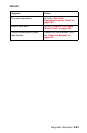
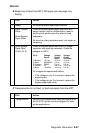
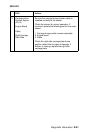
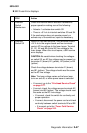
2 Carriage Unit
Block Assembly
Carriage Unit
Motor Idler Gear
Right Carriage
Unit Plate
Carriage
Assembly
Check the carriage unit motor idler gear for
signs of wear or breakage. If the motor idler
gear is good, check the right side carriage plate
for signs of broken teeth or wear on the plate
gear.
Check the carriage for correct operation. If
problems are found, repair as necessary.