


2-46 Service Manual
5016-001
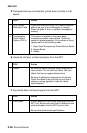
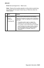
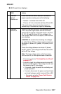
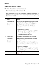
2 Interlock Switch
S2
Switch S2 has two functions. Two terminals control
+24 V dc to the engine board and four terminals
control the AC line voltage to the fuser lamps.
Terminal A3 (red wires) and terminal B3 (blue
wires) control the +24 V dc supply to the engine
board. When this circuit opens, a Close Door
message displays.
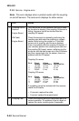
CAUTION: Be careful when checking the voltages
on switch S2, as the AC line voltage may be
present on terminals A1 (brown), B1 (yellow), A2
(brown) or B2 (yellow).
Check the voltage at terminal B3 (blue wires). It
should read approximately +24 V dc.
• If incorrect, go to the “Printhead Service
Check” on page 2-77.
• If correct, check the voltage on switch terminal
A3 (red wires).
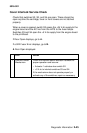
• If incorrect, check the switch for continuity
and proper operation.
• If correct, check the cable from the wires.
• If incorrect, check the switch for continuity
and proper operation.
• If correct, check the cable from the switch
to the engine board.
• If incorrect, replace the cable.
• If correct, replace the engine board.
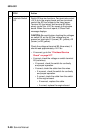
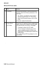
FRU Action