


2-74 Service Manual
5016-001
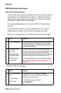
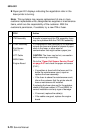
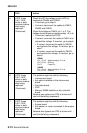
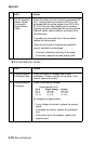
5 LVPS Fuses
F401, F402
either or both
continue to blow
after being
replaced.
(Continued)
Check the AC line voltage on the LVPS at
connectors CN404 and CN405.
• If incorrect, go to step 6.
• If correct, disconnect the cables to CN401,
CN402 and CN403.
Check the voltage at CN401 pin 1 or 2. The
voltage should measure approximately +5 V dc.
• If incorrect, replace the LVPS.
• If correct, reconnect the cable to CN401 and
recheck the voltage. If incorrect, go to step 6.
• If correct, reconnect the cable to CN402
and recheck the voltage. If incorrect, go to
step 7.
• If correct, reconnect the cable to CN403
and recheck the voltage. If incorrect, go to
step 8.
CN401
Pin 1, Pin 2 Approximately +5 V dc
Pin 3, Pin 4 Ground
Pin 5 Fuser On
CN402
Pin 1, Pin 2 Approximately +5 V dc
Pin 3, Pin 4 Ground
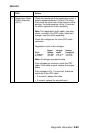
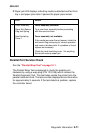
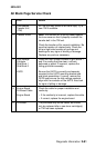
6 LVPS Fuses
F401, F402
either or both
continue to blow
after being
replaced.
(Continued)
The problem might be with the following:
• Interconnect board.
• Any option installed on the interconnect
board.
• Controller board.
• COS.
• Memory DIMM installed on the controller
board.
Remove and replace one FRU at a time until
you find the failing component.
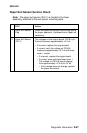
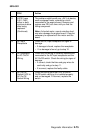
7 LVPS Fuses
F401, F402
either or both
continue to blow
after being
replaced.
(Continued)
The problem might be with the following:
• Engine board
• Any sensor or motor connected to the engine
board.
Remove and replace one FRU at a time until
you find the failing component.
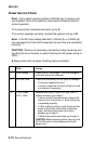
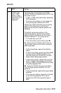
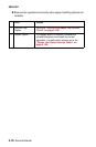
FRU Action