


2-78 Service Manual
5016-001
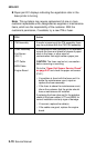
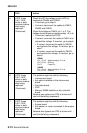
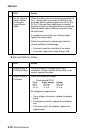
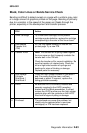
B 934 and 935 Error Codes
2 S3, S4 Interlock
Switch Cables.
Printhead to
Engine Board
Cable
Check the cable from the interlock microswitch S3
Pin 1 (orange lead) to connector CNLS2 on the
printhead and the yellow jumper from S3 Pin 2 to
S4 Pin 2. Be sure these cables are connected
properly and are not damaged. Be sure to note the
interlock switch cable connector mounted to the
left side frame.
If a problem is found with any of these cables,
replace the failing cable.
Check the printhead to engine board cable for
correct installation and damage.
• If correct, check the continuity of the cable.
• If incorrect, replace the cable and go to B.
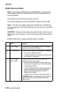
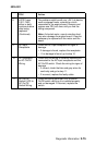
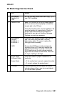
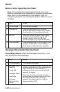
FRU Action
1 Engine Board to
Printhead Cable
Check the cable for damage and correct
installation. Check continuity of the cable. If not
correct, replace the cable.
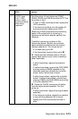
2 Engine Board to
Printhead
Check the following voltages:
Engine board CN14
Pin # Signal Voltage Voltage
Pin 5 +24 V dc +24 V dc
Pin 6 +5 V dc +5 V dc
Pin 19 +5 V dc +5 V dc
All voltages are approximate.
• If any voltage is incorrect, replace the engine
board.
• If voltages are correct, replace the printhead
first.
• If this does not fix the problem, replace the
engine board.
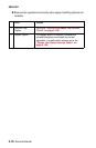
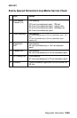
FRU Action