


2-118 Service Manual
5016-001
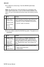
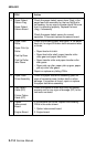
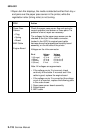
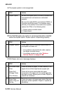
I Paper Jam 24x displays, the media is detected and fed from tray x
and jams over the paper pass sensor in the printer, while the
registration roller (timing roller) is not turning.
FRU Action
1 Paper Pass
Sensor:
• Flag
• Spring
• Board
MK2 Cable
Engine Board
Check the paper pass sensor flag and spring for
correct operation and broken or loose parts. If a
problem is found, repair as necessary.
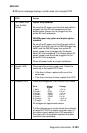
The voltages for the paper pass sensor can be
checked at the 6 pin inline cable connector,
located in the HVPS to engine board cable
harness above the temperature/humidity board
assembly, on the left side of the printer.
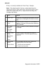
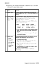
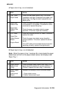
Voltages on the inline connector.
Pin # Voltage Voltage
Static Feeding
3 (Orange) +5 V dc +5 V dc
4 (Blue) +5 V dc 0 V dc to +5
5 (Brown) +5 V dc 0 V dc to +5
6 (Green) 0 V dc 0 V dc
Note: All voltages are approximate.
• If the voltage on pin 3 is incorrect, check
continuity of the cable. If incorrect and If the
cable is good, replace the engine board.
• If the voltage on pin 3 is correct but the voltage
on pin 4 is incorrect, replace the following parts
in the order shown:
1. Paper pass sensor board assembly
2. Engine board
3. MK 2 cable