


Diagnostic Information 2-113
5016-001
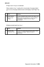
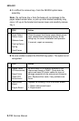
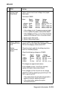
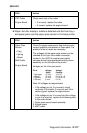
2 Option Paper
Feed Motor
Option interconnect board voltage chart paper
feed motor.
Connector CN802
Pin # Signal Voltage Voltage
Voltage Signal Signal
Static Operating
1 (Brown) PH3B- +24 V dc +22.0 to +25.5 V dc
2 (Red) VP +24 V dc +24 V dc
3 (Blue) PH3B+ +24 V dc +22.0 to +25.5 V dc
4 (Yellow) PH3A+ +24 V dc +22.0 to +25.5 V dc
5 (Red) PH3A- +24 V dc +22.0 to +25.5 V dc
• If the voltage on pin 2 measures approximately
0 V dc, replace the option interconnect board.
• If the voltages on Pins 1, 3, 4 or 5 are incorrect,
replace the following FRUs in the order shown:
1. Option paper feed motor
2. Option interconnect board
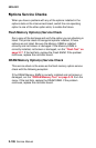
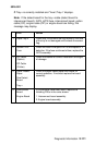
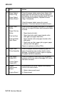
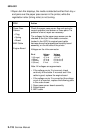
3 Paper Feed Unit
Clutches CL2 or
CL3
Option
Interconnect
Board
If a 242 Paper Jam message displays, check
clutch CL2. If a 243 Paper Jam message Clutches
CL2 or CL3 displays, check clutch CL3.
Check the clutch cable for the failing tray to be
sure it is installed properly.
Check the following voltages on CN803:
Pin # Signal Voltage Voltage
Voltage Static Clutch Picked
1 (Red) VP +24 V dc +24 V dc
2 (Black) -SL6ON +24 V dc +24 V dc - 0 V dc
3 (Red) VP + 24 V dc +24 V dc
4 (Blue) -SL7ON +24 V dc +24 V dc - 0 V dc
All voltages are approximate values.
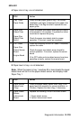
If the voltages on pins 1 and 3 are incorrect,
replace the option interconnect board.
If the voltages on Pins 2 and 4 do not change,
check the clutch by applying a ground to pin 2 for
CL2, or pin 4 for CL3.
• If the clutch does not pick when the ground is
applied to the pin, replace the clutch.
• If the clutch picks, replace the option
interconnect board.
FRU Action