


Diagnostic Information 2-65
5016-001
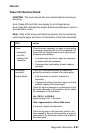
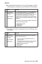
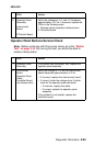
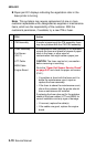
Operator Panel Buttons Service Check
Note: Before continuing with this service check, go to the “Button
Test” on page 3-10. By running this test, you should be able to
isolate a failing button.
5 Operator Panel
Assembly
Interconnect
Board
COntroller Board
Verify the voltages at J1-1 and J1-3 measure
approximately +5 V dc. If incorrect, replace the
FRUs in the following order:
1. Operator panel assembly interface board
2. Controller board
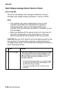
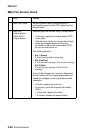
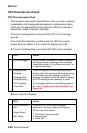
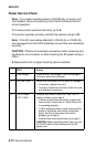
FRU Action
1 Operator Panel
Assembly
If any button fails the Button Test, replace the
operator panel assembly.
2 Interconnect
Board
Operator Panel
Cable
Controller Board
(no buttons work)
Verify the voltage at J1-5 on the interconnect
board measures approximately +5 V dc.
• If incorrect, replace the interconnect board.
• If correct, check the voltage at pin 5 (white
lead) on the operator panel connector.
• If incorrect, replace the cable.
• If correct, replace the operator panel
assembly.
If the problem is not located, replace the
controller board.
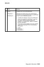
FRU Action