Chapter 4 Register Map and Descriptions
©
National Instruments Corporation 4-13 AT-MIO-16X User Manual
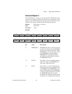
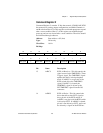
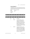
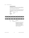
Command Register 3
Command Register 3 contains 16 bits that control the ADC link to the
AT-DSP2200, digital I/O port, interrupt and DMA modes, and interrupt
channel selection. The contents of this register are defined to be cleared
upon power up and after a reset condition.
Address: Base address + 04 (hex)
Type: Write-only
Word Size: 16-bit
Bit Map:
Bit Name Description
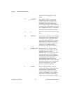
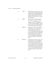
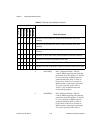
15 ADCDSP ADC DSP Link Enable—This bit
controls the serial link from the A/D
converter to the AT-DSP2200. If
ADCDSP is set, then the serial link is
enabled. Data from channels that have
been marked in the channel configuration
memory will be transmitted over the
RTSI bus. If ADCDSP is cleared, the
serial RTSI link is disabled, irrespective
of the marking of channels in the channel
configuration memory.
14 DIOPBEN Digital I/O Port B Enable—This bit
controls the 4-bit digital output port B.
If DIOPBEN is set, the Digital Output
Register drives the DIO<8..5> digital
lines at the I/O connector. If DIOPBEN
is cleared, the Digital Output Register
drivers are set to a high-impedance state;
therefore, an external device can drive
the DIO<8..5> digital lines.
76 5
ADCREQ
43
DAC0REQ
2
INTCHB2
10
INTCHB1DMACHB DAC1REQ INTCHB0DRVAIS
15
MSB
LSB
14 13
DIOPBEN
12 11
DMATCINT
10
DAQCMPLINT
98
I/O_INTADCDSP DIOPAEN DMACHADACCMPLINT


