Chapter 5 Programming
AT-MIO-16X User Manual 5-32
©
National Instruments Corporation
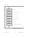
sequence of events continues ad infinitum and does not stop until the
update signal is removed or the DAC circuitry is cleared.
This sequence requires that the GATE2SEL signal in addition to the
SRC3SEL signal be set in Command Register 4. This allows Counter 1
to count the buffer retransmit signals from the source line of Counter 3
while Counter 2 is gated by the signal at its own gate pin.
Waveform Generation Programming Functions
This section provides a detailed explanation of the programming
functions necessary to generate synchronously timed analog output
waveforms.
Clearing the Analog Output Circuitry
This involves clearing the TMRREQ, DACCOMP, and DMATCA or
DMATCB bits in the Status Register. To do this, access the TMRREQ
Clear, DAC Clear, and if necessary, the DMATCA or DMATCB Clear
registers.
Selecting the Internal Update Counter
Select the desired signal at the RTSI switch to be used for updating the
DACs. OUT1, OUT2, OUT3 (available as EXTCONV*), and OUT5 are
available for updating. To route these update signals, the A side pin of
the RTSI switch must be internally routed to the B side, or trigger side.
Select a trigger line that is not being used. The signal must be routed
from the selected B side trigger line to the A4 pin on the RTSI switch.
All of this is done in one programming sequence by shifting a 56-bit
value to the RTSI switch. See the RTSI Bus Trigger Line Programming
Considerations section later in this chapter.
Notice that if OUT5 is to be used for updating, it does not need to be
routed across the RTSI switch. In this case only is it sufficient to enable
A4DRV to drive pin A4 of the RTSI switch with OUT5.
Programming the Update-Interval Counter
Select the appropriate counter (1, 2, 3, or 5) from the Am9513A
Counter/Timer to be used for updating the DACs. Active low pulsing
and no gating should be part of the mode programmed. To program the
update-interval counter, complete the following programming


