©
National Instruments Corporation 4-1 AT-MIO-16X User Manual
Chapter
4
Register Map and
Descriptions
This chapter describes in detail the address and function of each of the
AT-MIO-16X control and status registers.
Note:
If you plan to use a programming software package such as NI-DAQ
or LabWindows/CVI with your AT-MIO-16X board, you need not read this
chapter. However, you will gain added insight into your AT-MIO-16X
board by reading this chapter.
Register Map
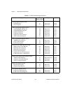
The register map for the AT-MIO-16X is shown in Table 4-1. This table
gives the register name, the register offset address, the type of the
register (read-only, write-only, or read-and-write) and the size of the
register in bits. The actual register address is obtained by adding the
appropriate register offset to the I/O base address of the AT-MIO-16X.
Registers are grouped in the table by function. Each register group is
introduced in the order shown in Table 4-1, then described in detail,
including a bit-by-bit description.
Table 4-1.
AT-MIO-16X Register Map
Register Name Offset
Address (Hex)
Type Size
Configuration and Status Register Group
Command Register 1
Command Register 2
Command Register 3
Command Register 4
Status Register 1
Status Register 2
0
2
4
6
18
1A
Write-only
Write-only
Write-only
Write-only
Read-only
Read-only
16-bit
16-bit
16-bit
16-bit
16-bit
16-bit
Analog Input Register Group
ADC FIFO Register
CONFIGMEM Register
0
8
Read-only
Write-only
16-bit
16-bit


