Chapter 2 Configuration and Installation
©
National Instruments Corporation 2-19 AT-MIO-16X User Manual
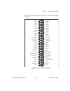
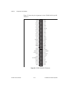
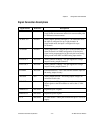
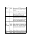
The signals on the connector can be classified as analog input signals,
analog output signals, digital I/O signals, digital power connections, or
timing I/O signals. Signal connection guidelines for each of these
groups are given in the following section.
Analog Input Signal Connections
AI GND is an analog input common signal that is routed directly to
the ground tie point on the AT-MIO-16X. These pins can be used for a
general analog power ground tie point to the AT-MIO-16X if necessary.
In NRSE mode, AI SENSE is connected internally to the negative (–)
input of the AT-MIO-16X PGIA. In the DIFF and RSE modes, this
signal is driven by AI GND or left unconnected.
Signal pins ACH<0..15> are tied to the 16 analog input channels of
the AT-MIO-16X. In single-ended mode, signals connected to
ACH<0..15> are routed to the positive (+) input of the AT-MIO-16X
PGIA. In differential mode, signals connected to ACH<0..7> are routed
to the positive (+) input of the AT-MIO-16X PGIA, and signals
connected to ACH<8..15> are routed to the negative (–) input of the
AT-MIO-16X PGIA.
Caution: Exceeding the differential and common-mode input ranges results in
distorted input signals. Exceeding the maximum input voltage rating can
result in damage to the AT-MIO-16X board and to the PC. National
Instruments is not liable for any damages resulting from such signal
connections.
Connection of analog input signals to the AT-MIO-16X depends on the
configuration of the AT-MIO-16X analog input circuitry and the type
of input signal source. With the different AT-MIO-16X configurations,
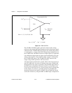
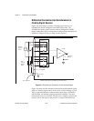
you can use the AT-MIO-16X PGIA in different ways. Figure 2-6
shows a diagram of the AT-MIO-16X PGIA.
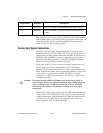
OUT5 DIG GND OUT5—This pin is from the Am9513A Counter 5 signal.
FOUT DIG GND Frequency Output—This pin is from the Am9513A FOUT
signal.
Signal Names Reference Descriptions


