Chapter 2 Configuration and Installation
©
National Instruments Corporation 2-41 AT-MIO-16X User Manual
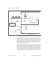
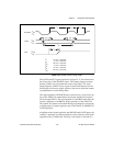
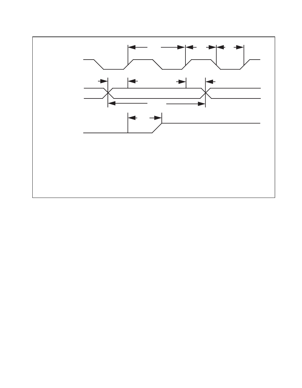
Figure 2-19. General-Purpose Timing Signals
The GATE and OUT signal transitions in Figure 2-17 are referenced to
the rising edge of the SOURCE signal. This timing diagram assumes
that the counters are programmed to count rising edges. The same
timing diagram, with the source signal inverted and referenced to the
falling edge of the source signal, applies to the case in which the counter
is programmed to count falling edges.
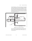
The signal applied at a SOURCE input can be used as a clock source by
any of the Am9513A counter/timers and by the Am9513A frequency
division output FOUT. The signal applied to a SOURCE input must not
exceed a frequency of 6 MHz for proper operation of the Am9513A.
The Am9513A counters can be individually programmed to count rising
or falling edges of signals applied at any of the Am9513A SOURCE or
GATE input pins.
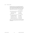
In addition to the signals applied to the SOURCE and GATE inputs, the
Am9513A generates six internal timebase clocks from the clock signal
supplied by the AT-MIO-16X. The base clock signal is selected by a
sp
ttt
SOURCE
V
IH
V
IL
V
IH
V
IL
sc
sp
t
gsu
t
gh
t
gw
GATE
t
out
OUT
V
OH
V
OL
sc
t
t
t
t
t
t
145 nsec minimum
sp
70 nsec minimum
gsu
100 nsec minimum
gh
10 nsec minimum
gw
145 nsec minimum
out
300 nsec maximum


