Chapter 2 Configuration and Installation
AT-MIO-16X User Manual 2-10
©
National Instruments Corporation
• Multiplexer control is configured to control up to 16 input
channels.
Note: The NRSE input mode is the only mode in which the AI SENSE signal
from the I/O connector is used as an input. In all other modes, AI SENSE
is either programmed to be unused or driven with the board analog input
ground.
Considerations for using the NRSE input configuration are discussed in
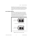
the Signal Connections section later in this chapter. Figure 2-8 shows a
schematic diagram of this configuration.
Input Polarity and Input Range
The AT-MIO-16X has two polarities: unipolar input and bipolar input.
Unipolar input means that the input voltage range is between 0 and V
ref
where V
ref
is a positive reference voltage. Bipolar input means that the
input voltage range is between –V
ref
and +V
ref
. The AT-MIO-16X has
a maximum unipolar input range of 10 V, and a maximum bipolar input
range of 20 V (±10 V). Polarity and range settings are programmed on
a per channel basis through the configuration memory register.
Considerations for Selecting Input Ranges
Input polarity and range selection depend on the expected input range
of the incoming signal. A large input range can accommodate a large
signal variation but lowers the voltage resolution. Choosing a smaller
input range increases the voltage resolution but may result in the input
signal going out of range. For best results, the input range should be
matched as closely as possible to the expected range of the input signal.
For example, if the input signal is certain not to be negative (below
0 V), a unipolar input is best. However, if the signal is ever negative,
inaccurate readings will occur if unipolar input polarity is used.
The software-programmable gain on the AT-MIO-16X increases its
overall flexibility by matching the input signal ranges to those that the
AT-MIO-16X analog-to-digital converter (ADC) can accommodate.
The AT-MIO-16X board has gains of 1, 2, 5, 10, 20, 50, and 100 and is
suited for a wide variety of signal levels. With the proper gain setting,
the full resolution of the ADC can be used to measure the input signal.
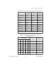
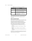
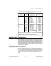
Table 2-4 shows the overall input range and precision according to the
input range configuration and gain used.


