Chapter 2 Configuration and Installation
©
National Instruments Corporation 2-3 AT-MIO-16X User Manual
The PC defines accesses to plug-in boards to be I/O mapped accesses
within the I/O space of the computer. Locations are either written to or
read from as bytes or words. Each register in the register set is mapped
to a certain offset from the base address selection of the board as read
or write, and as a word or byte location as defined by the decode
circuitry.
Base I/O Address Selection
The AT-MIO-16X is configured at the factory to a base I/O address
of 220 hex. This base address setting is suitable for most systems.
However, if your system has other hardware at this base I/O address,
you must change either the AT-MIO-16X base address DIP switch or
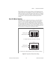
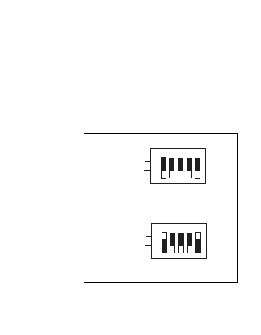
the other hardware base address to avoid a conflict. Figure 2-3 shows a
graphical representation of the base address selection DIP switch, and
also shows how to reconfigure the selected base address.
Figure 2-3.
Example Base I/O Address Switch Settings
A. Switches Set to Base I/O Address of Hex 000
Switch down for 0
Switch up for 1
B. Switches Set to Base I/O Address of Hex 220 (Factory Setting)
F
O
F
O
N
12345
U112
Switch down for 0
Switch up for 1
F
O
F
O
N
12345
U112
A6
A8
A9
A5
A7
A6
A8
A9
A5
A7


