Chapter 2 Configuration and Installation
©
National Instruments Corporation 2-27 AT-MIO-16X User Manual
and 15 are on pins 17 and 18, which are the farthest analog inputs
from AI GND. The sensitivities to noise of the other channels in the
middle are between those of Channels 0 and 15 and vary according to
their distance from AI GND. If AI SENSE is used as a reference instead
of AI GND, the sensitivity to noise still varies among the channels,
but in this case according to their distance from AI SENSE, pin 19
(so Channel 15 is the least sensitive and Channel 0 is the most
sensitive).
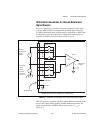
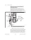
Single-Ended Connections for Floating Signal
Sources (RSE Configuration)
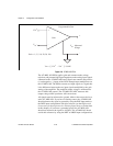
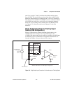
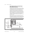
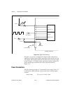
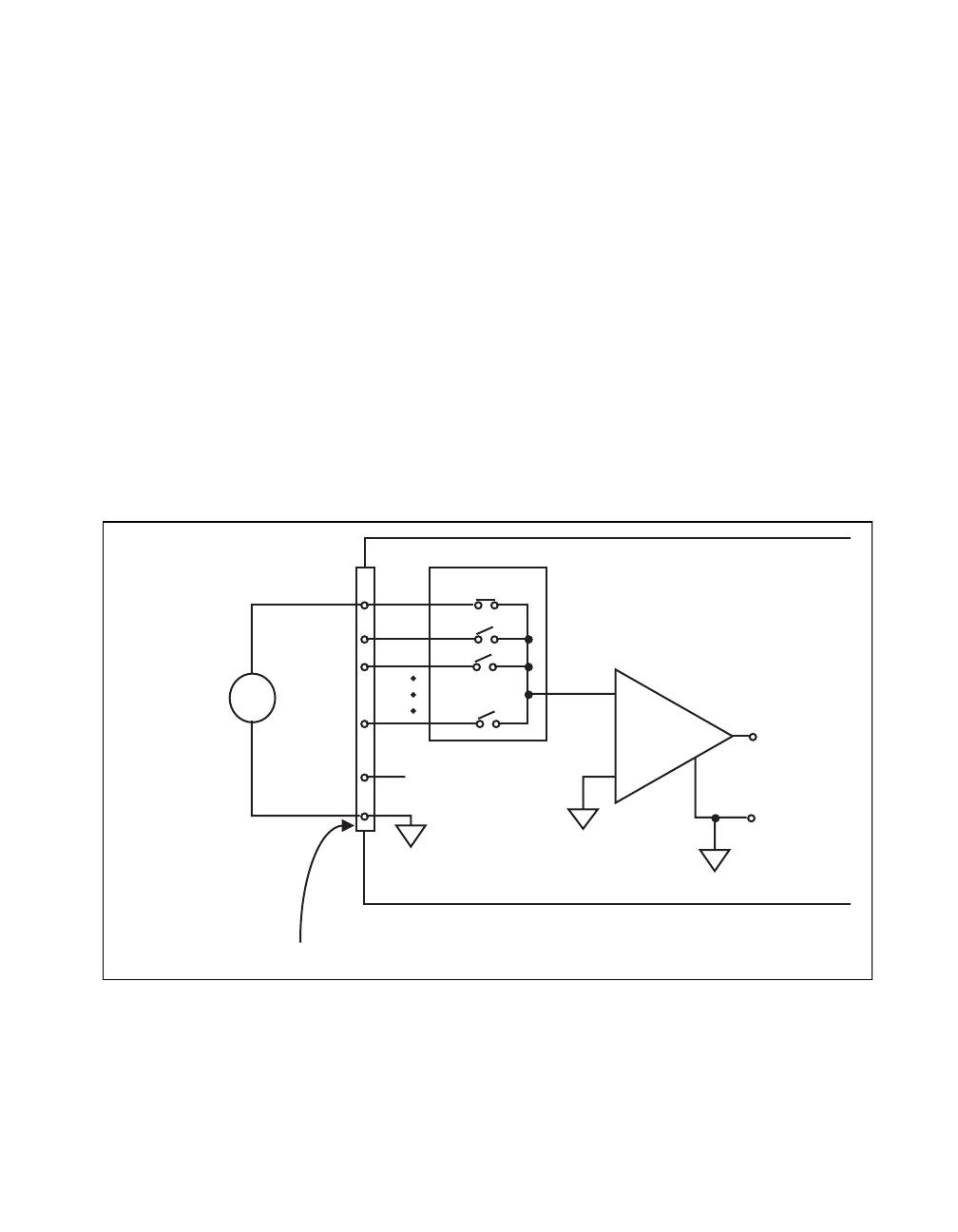
Figure 2-9 shows how to connect a floating signal source to an
AT-MIO-16X board configured for single-ended input. The
AT-MIO-16X analog input circuitry must be configured for RSE input
to make these types of connections. Configuration instructions are
included in Chapter 4, Register Map and Descriptions.
Figure 2-9.
Single-Ended Input Connections for Nonreferenced or Floating Signals
ACH<0..15>
Input Multiplexer
AI GND
AI SENSE
V
s
-
+
I/O Connector
AT-MIO-16X Board in the RSE Input Configuration
m
-
+
-
V
Measured
Voltage
PGIA
+
Nonreferenced
or Floating
Signal
Source
Gain


