Chapter 5 Programming
AT-MIO-16X User Manual 5-38
©
National Instruments Corporation
Figure 3-19 in Chapter 3, Theory of Operation, diagrams the
AT-MIO-16X RTSI switch connections.
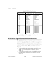
RTSI Switch Signal Connection Considerations
The AT-MIO-16X board has a total of nine signals connected to the
seven A-side pins of the RTSI crossbar switch. These same signals also
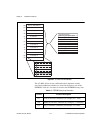
appear at the AT-MIO-16X I/O connector. As shown in Table 5-2, two
AT-MIO-16X signals are connected to pin A2, and two signals are
connected to pin A4. The routing of these signals is further controlled
by the bits A4DRV, A4RCV, A2DRV, and A2RCV in Command
Register 2.
• To drive the RTSI switch pin A2 with the signal OUT2, set the
A2DRV bit in Command Register 2. Otherwise, clear the
A2DRV bit.
• To drive the signal GATE1 from pin A2 of the RTSI switch, set
the A2RCV bit in Command Register 2. Otherwise, clear the
A2RCV bit.
Table 5-2.
RTSI Switch Signal Connections
RTSI Switch Pin Signal Name Signal Direction
A Side
A0
A1
A2
A2
A3
A4
A4
A5
A6
EXTCONV*
FOUT
OUT2
GATE1
SOURCE5
OUT5
TMRTRIG*
OUT1
EXTTRIG*
Bidirectional
Output
Output
Input
Bidirectional
Output
Input
Bidirectional
Bidirectional
B Side
B0
B1
B2
B3
B4
B5
B6
TRIGGER0
TRIGGER1
TRIGGER2
TRIGGER3
TRIGGER4
TRIGGER5
TRIGGER6
Bidirectional
Bidirectional
Bidirectional
Bidirectional
Bidirectional
Bidirectional
Bidirectional


