Chapter 3 Theory of Operation
AT-MIO-16X User Manual 3-8
©
National Instruments Corporation
bipolar modes, and these values are also permanently stored in the
EEPROM. Calibration constants can be read from the EEPROM then
written to the calibration DACs that adjust pregain offset, postgain
offset, and gain errors associated with the analog input section. There
is a 12-bit pregain offset calibration DAC, an 8-bit coarse postgain
offset calibration DAC, an 8-bit fine postgain offset calibration DAC,
an 8-bit coarse gain calibration DAC, and an 8-bit fine gain calibration
DAC. Functions are provided with the board to calibrate the analog
input section, access the EEPROM on the board, and write to the
calibration DACs. When the AT-MIO-16X leaves the factory, locations
96 through 127 of the EEPROM are protected and cannot be modified.
Locations 0 through 95 are unprotected and can be used to store
alternate calibration constants for the differing conditions under which
the board is used. Refer to Chapter 6, Calibration Procedures, for
additional calibration information.
Data Acquisition Timing Circuitry
This section details the different methods of acquiring A/D data from a
single channel or multiple channels. Prior to any of these operations, the
channel, gain, mode, and range settings must be configured. This is
accomplished through writing to a register in the AT-MIO-16X register
set.
Single-Read Timing
The simplest method of acquiring data from the A/D converter is to
initiate a single conversion and then read the resulting value from the
ADC FIFO buffer after the conversion is complete. A single conversion
can be generated three different ways: applying an active low pulse to
the EXTCONV* pin of the I/O connector, generating a falling edge on
the sample-interval counter output pin (Counter 3 of the Am9513A
Counter/Timer), or strobing the appropriate register in the
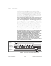
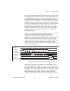
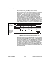
AT-MIO-16X register set. Any one of these operations will generate
the timing shown in Figure 3-4. The ADC_BUSY* signal status can
be monitored through a status register on the AT-MIO-16X.
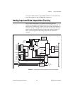
Figure 3-4.
ADC Conversion Timing
CONVERT*
ADC_BUSY*
FIFO_LD*


