Chapter 4 Register Map and Descriptions
©
National Instruments Corporation 4-21 AT-MIO-16X User Manual
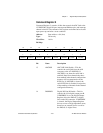
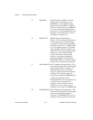
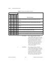
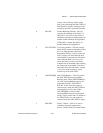
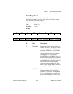
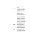
13 DAC1DSP DAC 1 DSP Link Enable—This bit
controls the serial link from the
AT-DSP2200 to DAC 1 of the analog
output section. If DAC1DSP is set, then
the serial link is enabled. Data is sent
from the AT-DSP2200 over the RTSI bus
and is accepted by DAC 1. If DAC1DSP
is cleared, the serial RTSI link is
disabled.
12 DAC0DSP DAC 0 DSP Link Enable—This bit
controls the serial link from the
AT-DSP2200 to DAC 0 of the analog
output section. If DAC0DSP is set, then
the serial link is enabled. Data is sent
from the AT-DSP2200 over the RTSI bus
and is accepted by DAC 0. If DAC0DSP
is cleared, the serial RTSI link is
disabled.
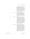
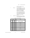
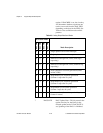
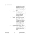
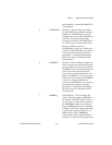
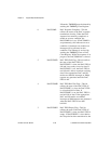
11-8 DACMB<3..0> DAC Mode Select—These bits control
the mode used to and updating the DACs.
DACMB3 is used to select the number of
reads from the DAC FIFO per update
signal, when in waveform generation
modes. If DACMB3 is clear, there will
be only one read of the DAC FIFO per
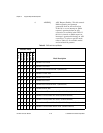
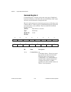
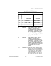
Table 4-5. Board and RTSI Clock Selection
Bit Pattern Effect
CLKMODEB1
CLKMODEB0
RTSI Clock Board Clock
X 0 No connection Internal, 10 MHz
0 1 Internal, 10 MHz Internal, 10 MHz
1 1 Driven onto board clock Received from RTSI
clock


