Appendix B I/O Connector
©
National Instruments Corporation B-5 AT-MIO-16X User Manual
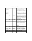
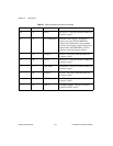
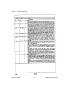
8, 14 34, 35 +5 V +5 VDC Source—These pins are fused for
up to 1 A of +5 V supply.
46 36 SCANCLK Scan Clock—This pin pulses once for each
A/D conversion in the scanning modes. The
low-to-high edge indicates when the input
signal can be removed from the input or
switched to another signal.
45 37 EXTSTROBE* External Strobe—Writing to the
EXTSTROBE Register results in a
minimum 500-nsec low pulse on this pin.
11 38 EXTTRIG* External Trigger—In posttrigger data
acquisition sequences, a high-to-low edge
on EXTTRIG* initiates the sequence. In
pretrigger applications, the first high-to-low
edge of EXTTRIG* initiates pretrigger
conversions while the second high-to-low
edge initiates the posttrigger sequence.
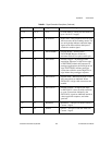
10 39 EXTGATE* External Gate—When EXTGATE* is low,
A/D conversions are inhibited. When
EXTGATE* is high, A/D conversions are
enabled.
43 40 EXTCONV* External Convert—A high-to-low edge
on EXTCONV* causes an A/D conversion
to occur. Conversions initiated by the
EXTCONV* signal are inhibited outside of
a data acquisition sequence, and when
gated off.
42 41 SOURCE1 SOURCE1—This pin is from the Am9513A
Counter 1 signal.
41 42 GATE1 GATE1—This pin is from the Am9513A
Counter 1 signal.
Table B-1. Signal Connection Descriptions (Continued)
68-Pin Pins 50-Pin Pins Signal Names Descriptions


