Chapter 2 Configuration and Installation
AT-MIO-16X User Manual 2-34
©
National Instruments Corporation
EXTCONV* Signal
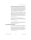
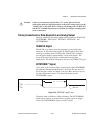
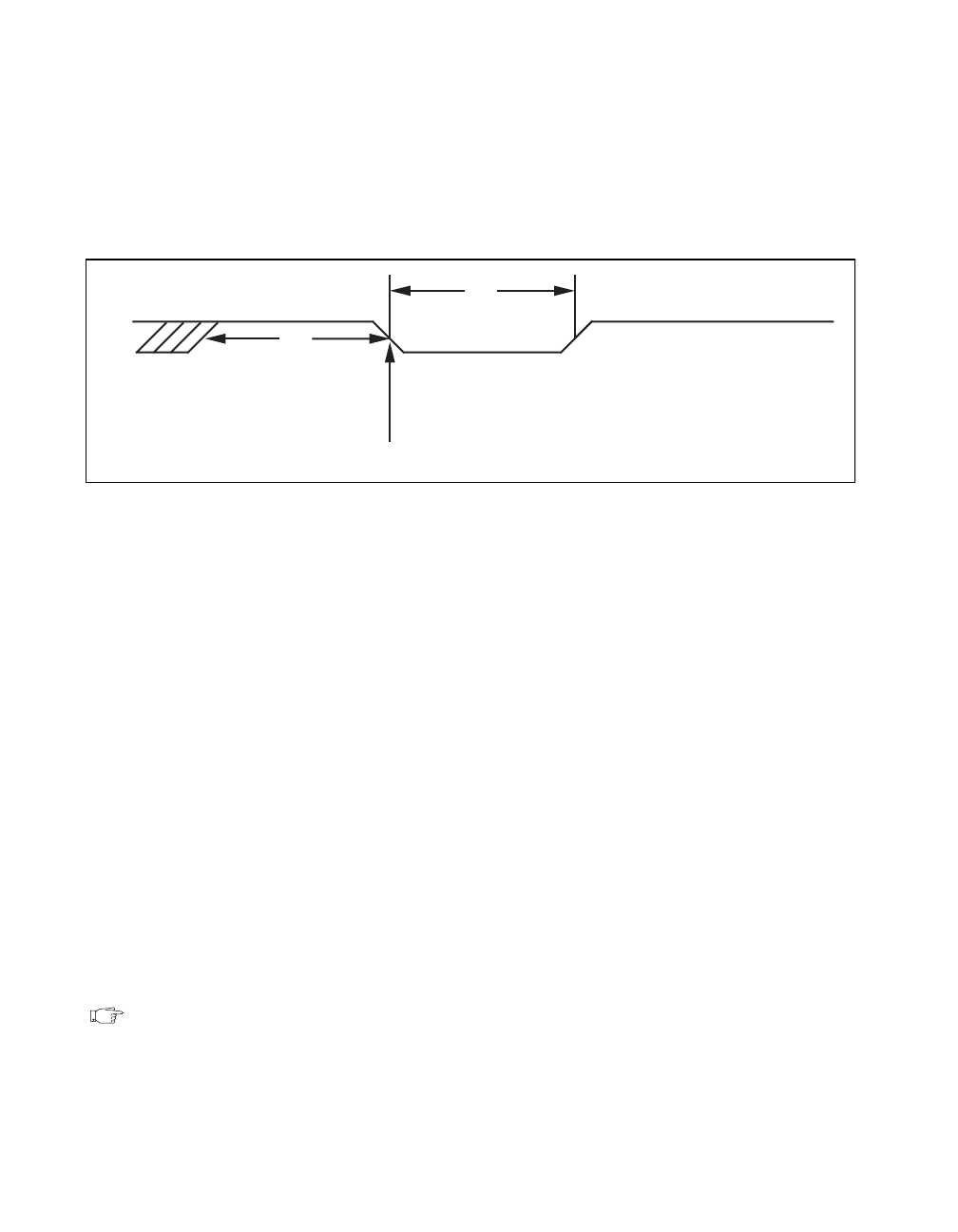
A/D conversions can be externally triggered with the EXTCONV* pin.
Applying an active low pulse to the EXTCONV* signal initiates an A/D
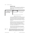
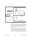
conversion. Figure 2-14 shows the timing requirements for the
EXTCONV* signal.
Figure 2-14.
EXTCONV* Signal Timing
The minimum allowed pulse width is 50 ns. The ADC switches to hold
mode within 100 ns of the high-to-low edge. This hold mode delay time
is a function of temperature and does not vary from one conversion to
the next. There is no maximum pulse width limitation. EXTCONV*
should be high for at least one conversion period before going low. The
EXTCONV* signal is one HCT load and is pulled up to +5 V through a
10-kΩ resistor.
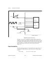
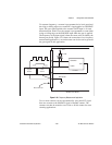
EXTCONV* is also driven by the output of Counter 3 of the Am9513A
Counter/Timer. This counter is also referred to as the sample-interval
counter. The output of Counter 3 and the RTSI connection to
EXTCONV* must be disabled to a high-impedance state if A/D
conversions are to be controlled by pulses applied to the EXTCONV*
pin. If Counter 3 is used to control A/D conversions, its output signal
can be monitored at the EXTCONV* pin.
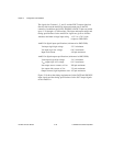
A/D conversions generated by either the EXTCONV* signal or the
sample-interval counter are inhibited outside of a data acquisition
sequence and when gated by either the hardware (EXTGATE*) signal
or software command register gate.
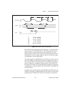
Note: EXTCONV* and the output of Counter 3 of the Am9513A are physically
connected together on the AT-MIO-16X. If Counter 3 is used in an
application, the EXTCONV* signal must be left undriven. Conversely,
if EXTCONV* is used in an application, Counter 3 must be disabled.
t
w
50 nsec minimum
ADC switches to hold mode within 100 nsec from this point
V
IL
V
IH
t
w
t
w


