Chapter 2 Configuration and Installation
©
National Instruments Corporation 2-31 AT-MIO-16X User Manual
Digital I/O Signal Connections
The digital lines ADIO<0..3> are connected to digital I/O port A. The
digital lines BDIO<0..3> are connected to digital I/O port B. DIG GND
is the digital ground pin for both digital I/O ports. Ports A and B can be
programmed individually to be inputs or outputs.
The following specifications and ratings apply to the digital I/O lines.
Absolute maximum voltage input rating 5.5 V with respect to
DIG GND
Digital input specifications (referenced to DIG GND):
V
IH
input logic high voltage 2 V minimum
V
IL
input logic low voltage 0.8 V maximum
I
IH
input current load,
logic high input voltage 40 µA maximum
I
IL
input current load,
logic low input voltage –120 µA maximum
Digital output specifications (referenced to DIG GND):
V
OH
output logic high voltage 2.4 V minimum
V
OL
output logic low voltage 0.5 V maximum
I
OH
output source current,
logic high 2.6 mA maximum
I
OL
output sink current, logic low 24 mA maximum
With these specifications, each digital output line can drive 11 standard
TTL loads and over 50 LS TTL loads.
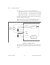
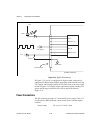
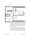
Figure 2-12 depicts signal connections for three typical digital I/O
applications.


