Chapter 5 Programming
AT-MIO-16X User Manual 5-42
©
National Instruments Corporation
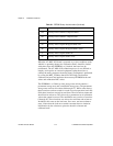
3. Program the DMA controller to service DMA requests from the
AT-MIO-16X board. Refer to the IBM Personal Computer AT
Technical Reference manual for more information on DMA
controller programming.
4. If a DMA terminal count is received after the DMA service, write 0
to either the appropriate DMATC Clear Register to clear the
DMATCA or DMATCB bits in Status Register 1.
Once steps 1 through 3 are completed, the DMA controller is
programmed to acknowledge requests. If analog input DMA is
programmed, the DMA controller automatically reads the ADC FIFO
Register whenever an A/D conversion result is available and then stores
the result in a buffer in memory. If the DMA controller has been
programmed for analog output updating, values from the buffer in
memory are automatically written to the DAC upon receipt of a DMA
request. If both analog input and output DMA is selected, then the DMA
controller reads the FIFO or writes to the DACs depending on which
channel requested a DMA transfer.
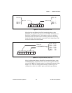
If single-channel interleaved DMA is selected for writing data to the
DACs, then one buffer services both DAC 0 and DAC 1. This is
accomplished by interleaving the data in the buffer. The first location in
the buffer should hold the first value to be transferred to DAC 0, the
second should hold the first value to be transferred to DAC 1, the third
should hold the second value to be transferred to DAC 0, and so on.
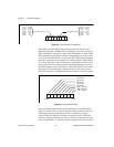
If dual-channel DMA operation has been selected for DMA requesting
service, DMA Channel A and memory buffer A (DMA A) are served
first. When a DMA terminal count is received, the board automatically
switches the DMA operation to DMA Channel B and memory buffer B
(DMA B). Therefore, the board can collect data to or from one buffer
and simultaneously service data in another buffer. If the DMA
controller is programmed for auto-reinitialize mode, DMA A and DMA
B are continuously served in turn.
If dual-channel DMA operation has been selected to service both analog
outputs, memory buffer A (DMA Channel A) and memory buffer B
(DMA Channel B) are concurrently serviced, with buffer A serving
DAC 0 and buffer B serving DAC 1.


