Chapter 4 Register Map and Descriptions
©
National Instruments Corporation 4-33 AT-MIO-16X User Manual
(0x8000 to 0x7FFF) when the ADC is in
bipolar mode.
The A/D conversion result can be returned from the ADC FIFO as a
two’s complement or straight binary value depending on the input mode
set by the CHAN_BIP bit in the configuration memory location for the
converted channel. If the analog input circuitry is configured for the
input range 0 to +10 V, straight binary format is implemented. Straight
binary format returns numbers between 0 and 65,535 (decimal) when
the ADC FIFO Register is read. If the analog input circuitry is
configured for the input ranges –10 to +10 V, two’s complement format
is used. Two’s complement format returns numbers between –32,768
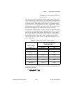
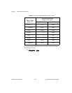
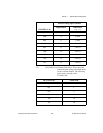
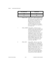
and +32,767 (decimal) when the ADC FIFO Register is read. Table 4-7
shows input voltage versus A/D conversion value for straight binary
format and 0 to +10 V input range. Table 4-8 shows input voltage
versus A/D conversion value for two’s complement format for –10 to
+10 V input range.
To convert from the ADC FIFO value to the input voltage measured, use
the following formula:
V = ADC reading
*
10 V
65,536 Gain
Table 4-7. Straight Binary Mode A/D Conversion Values
Input Voltage
(Gain = 1)
A/D Conversion Result
Range: 0 to 10 V
Decimal Hex
0.0 V 0 0000
152.6 µV 1 0001
2.5 V 16,384 4000
5.0 V 32,768 8000
7.5 V 49,152 C000
9.999847 V 65,535 FFFF


