Chapter 3 Theory of Operation
AT-MIO-16X User Manual 3-20
©
National Instruments Corporation
latch concurrently or separately. In this instance, the value written to the
DAC through the local latch is not updated until the update pulse trigger
occurs. If the RTSI latch is used to transfer serial data from the
AT-DSP2200 over the RTSI bus, no other transferring path is allowed.
In other words, data cannot be transmitted serially over the RTSI bus to
DAC Channel 0 and transferred through the FIFO to DAC Channel 1 at
the same time. These modes are mutually exclusive.
DAC Waveform Timing Circuitry
Waveform timing implies precise updating of the analog output DACs
to create a pure waveform without any jitter or uncertainty. This timing
is accomplished by posting updates to the DACs. Posted update mode
configures the DACs to buffer values written to them and update the
output voltage only after a trigger signal. This trigger signal can come
in the form of an internal counter pulse from Counters 1, 2, 3, or 5 of
the Am9513A Counter/Timer, it can be supplied from the
EXTTMRTRIG* signal at the I/O connector, or it can be obtained
by accessing a register in the AT-MIO-16X register set.
In the posted update mode, requests for writes to the DAC are generated
from the TMRREQ signal and can be acknowledged in one of three
ways: either polled I/O through monitoring the TMRREQ signal in
Status Register 1, interrupts, or DMA. All three response mechanisms
will have a delay associated with them in how fast they can respond to
the requesting signal. DMA will have the fastest response, followed by
polled I/O, and finally interrupts. The advantage of using interrupts is
that the CPU is not solely dedicated to monitoring Status Register 1 and
can simultaneously perform other tasks. If writes generated from these
requests updated the DAC immediately, there could be significant jitter
in the resulting output waveform, so values are written to a buffer where
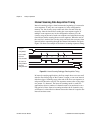
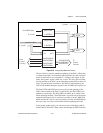
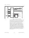
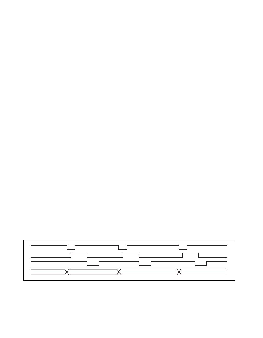
they are updated later with a precisely timed update signal. Figure 3-11
depicts the timing for the posted DAC update mode.
Figure 3-11.
Posted DAC Update Timing
Update Trigger
TMRREQ
DAC Write*
XY
Z
X-1 X YDAC Output


