Chapter 5 Programming
©
National Instruments Corporation 5-17 AT-MIO-16X User Manual
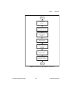
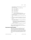
found in Appendix C, AMD Am9513A Data Sheet. Use one of the
following mode values:
8225 — Selects 5-MHz clock (from SOURCE2 pin)
8B25 — Selects 1-MHz clock
8C25 — Selects 100-kHz clock
8D25 — Selects 10-kHz clock
8E25 — Selects 1-kHz clock
8F25 — Selects 100-Hz clock
8525 — Selects signal at SOURCE5 input as clock
(counts the rising edge of the signal, 6 MHz maximum)
3. Write FF0B to the Am9513A Command Register to select the
Counter 3 Load Register.
4. Write 2 to the Am9513A Data Register to store the Counter 3 load
value.
5. Write FF44 to the Am9513A Command Register to load Counter 3.
6. Write FFF3 to the Am9513A Command Register to step Counter 3
down to 1.
7. Write the desired sample interval to the Am9513A Data Register to
store the Counter 3 load value:
– If the sample interval is between 2 and FFFF (65,535 decimal),
write the sample interval to the Am9513A Data Register.
– If the sample interval is 10000 (65,536 decimal), write 0 to the
Am9513A Data Register.
8. Write FF24 to the Am9513A Command Register to arm Counter 3.
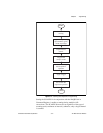
After you complete this programming sequence, Counter 3 is
configured to generate A/D conversion pulses as soon as application
of a trigger causes it to be enabled.
Programming the Sample Counter(s)
Counters 4 and 5 of the Am9513A Counter/Timer are used as the
sample counter. The sample counter tallies the number of A/D
conversions initiated by Counter 3 or EXTCONV* and inhibits
conversions when the desired sample count is reached. If the desired
sample count is 65,536 or less, only Counter 4 needs to be used, making
Counter 5 available for general-purpose timing applications. If the
desired sample count is greater than 65,536, both Counters 4 and 5 must
be used.


