Chapter 2 Configuration and Installation
AT-MIO-16X User Manual 2-18
©
National Instruments Corporation
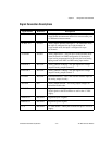
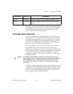
SCANCLK DIG GND Scan Clock—This pin pulses once for each A/D conversion in
the scanning modes. The low-to-high edge indicates when the
input signal can be removed from the input or switched to
another signal.
EXTSTROBE* DIG GND External Strobe—Writing to the EXTSTROBE Register
results in a minimum 500-nsec low pulse on this pin.
EXTTRIG* DIG GND External Trigger—In posttrigger data acquisition sequences, a
high-to-low edge on EXTTRIG* initiates the sequence. In
pretrigger applications, the first high-to-low edge of
EXTTRIG* initiates pretrigger conversions while the second
high-to-low edge initiates the posttrigger sequence.
EXTGATE* DIG GND External Gate—When EXTGATE* is low, A/D conversions
are inhibited. When EXTGATE* is high, A/D conversions are
enabled.
EXTCONV* DIG GND External Convert—A high-to-low edge on EXTCONV*
causes an A/D conversion to occur. Conversions initiated by
the EXTCONV* signal are inhibited outside of a data
acquisition sequence, and when gated off.
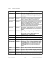
SOURCE1 DIG GND SOURCE1—This pin is from the Am9513A Counter 1 signal.
GATE1 DIG GND GATE1—This pin is from the Am9513A Counter 1 signal.
OUT1 DIG GND OUTPUT1—This pin is from the Am9513A Counter 1 signal.
EXTTMRTRIG* DIG GND External Timer Trigger—If selected, a high-to-low edge on
EXTTMRTRIG* results in the output DACs being updated
with the value written to them in the posted update mode.
EXTTMRTRIG* will also generate a timed interrupt if
enabled.
GATE2 DIG GND GATE2—This pin is from the Am9513A Counter 2 signal.
OUT2 DIG GND OUTPUT2—This pin is from the Am9513A Counter 2 signal.
SOURCE5 DIG GND SOURCE5—This pin is from the Am9513A Counter 5 signal.
GATE5 DIG GND GATE5—This pin is from the Am9513A Counter 5 signal.
Signal Names Reference Descriptions


