


MJ-1103/1104 © 2008, 2009 TOSHIBA TEC CORPORATION All rights reserved
DISASSEMBLY AND INSTALLATION
4 - 46
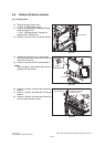
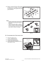
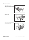
[D] Front transport roller / Rear transport roller
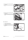
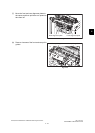
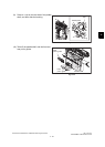
(11) Remove 1 clip and 10 E-rings. Then remove
6 paddles, 8 pins, 2 bushings. Then take off
the catching pad, catchi ng pad collar, spring,
gear and actuator.
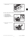
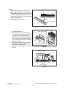
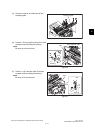
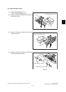
Notes:
• Install the catching pad, catching pad col-
lar and spring in the directions shown in
the figure.
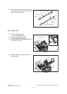
• When installing the paddle-1, paddle-2,
paddle-3, paddle-4, paddle-5 and paddle-
6, be sure that each star mark of the pad-
dles is seen as shown in the figure.
Fig. 4-126
Fig. 4-127
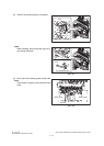
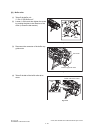
(1) Take off the stationary tray.
P.4-1 "[A] Stationary tray"
(2) Take off the Junction box unit.
P.4-13 "[A] Junction box unit"
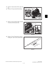
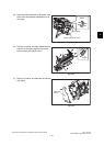
(3) Close the buffer unit-1 halfway and leave it.
Then remove 1 screw.
Fig. 4-128
Clip
Bushing
Bushing
Paddle
Paddle
Collar
Spring Catching pad
Actuator
Gear
Pin
Buffer unit-1
Screw