


3
© 2008, 2009 TOSHIBA TEC CORPORATION All rights reserved MJ-1103/1104
DESCRIPTION OF OPERATIONS
3 - 31
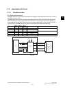
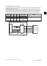
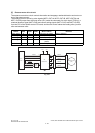
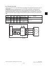
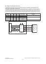
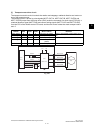
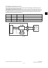
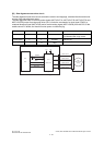
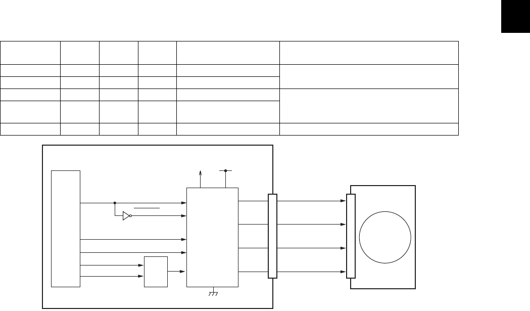
[I] Transport motor drive circuit
The transport motor drive circuit controls the rotation and stoppage, rotational direction and motor cur-
rent of the transport motor.
The transport motor is driven by pulse signals (MOT7-OUT1A, MOT7-OUT1B, MOT7-OUT2A and
MOT7-OUT2B) output from the motor driver (IC43) under the command of a clock signal (TIOCA0), a
rotational direction signal (MOT7-DIR) and current setting signals (MOT7-CUR1 and MOT7-CUR0)
from the CPU of the finisher control PC board, and thus this motor rotates the stack transport roller-1
and -2.
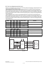
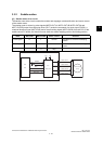
Fig. 3-36
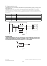
TIOCA0
MOT7-
DIR
MOT7-
CUR1
MOT7-
CUR0
Motor rotation Remarks
Clock signal H L H Normal (Low power) Paper is transported to the finishing posi-
tion.
Clock signal H L L Normal (Normal power)
Clock signal L L H Reverse (Low power) Paper is transported to the movable tray.
Clock signal L L L Reverse (Normal
power)
--H- Stop
IC21
CPU
TIOCA0
MOT7-OUT1A
VM
MOT7-OUT2A
MOT7-OUT1B
MOT7-OUT2B
SG
MOT7-DIR
24
4
1
21
5
20
16
13
P-RESET
P-RESET
3.3V
Transport motor
(M7)
IC43
Motor driver
Finisher control PC board
MOT7-CUR1
17
MOT7-CUR0
Current
control
circuit
CN10