


4
© 2008, 2009 TOSHIBA TEC CORPORATION All rights reserved MJ-1103/1104
DISASSEMBLY AND INSTALLATION
4 - 3
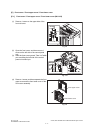
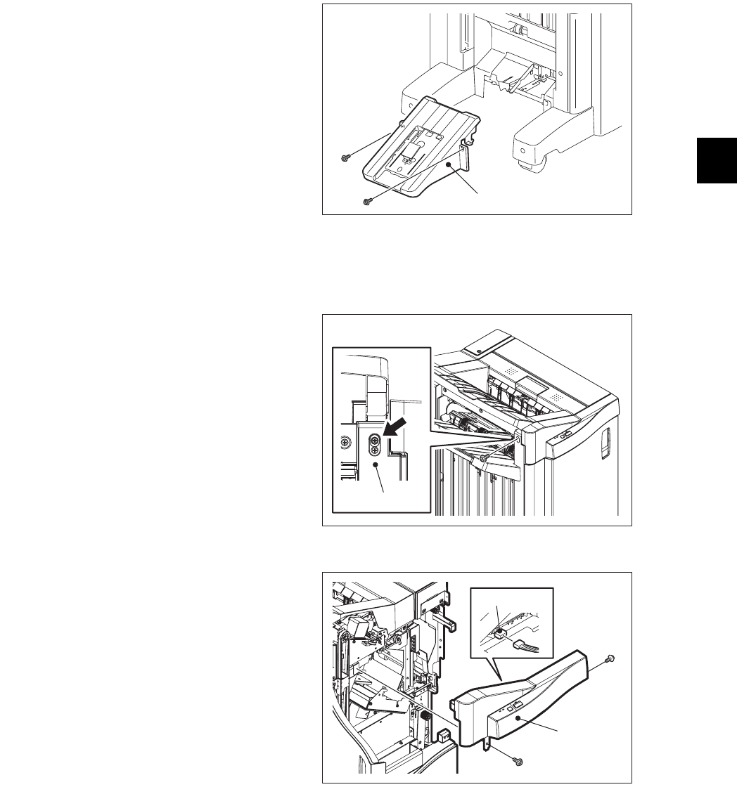
[D] Control panel unit
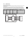
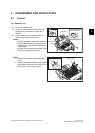
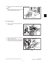
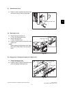
(3) Remove 2 screws, and then take off the sad-
dle tray.
Note:
When installing, hang the 2 hooks of the sad-
dle tray on the hole of the main unit.
Fig. 4-6
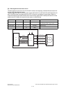
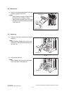
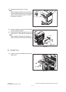
(1) Remove 1 screw on the upper side of the
front rail cover.
Fig. 4-7
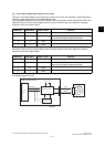
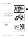
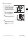
(2) Open the front cover (MJ-1103) or the front
upper cover (MJ-1104).
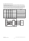
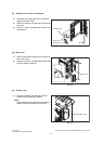
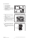
(3) Remove 2 screws, and then disconnect the
connector to take off the control panel unit.
Fig. 4-8
Saddle tray
Front rail cover
Connector
Control panel unit