


MJ-1103/1104 © 2008, 2009 TOSHIBA TEC CORPORATION All rights reserved
GENERAL DESCRIPTION
2 - 12
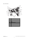
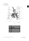
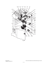
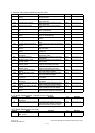
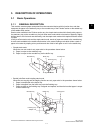
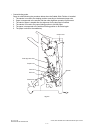
8. Sensors and switches (Saddle section: MJ-1104)
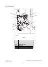
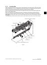
9. PC board (Finisher section : Common for MJ-1103/1104)
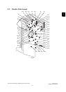
10.PC board (Saddle section: MJ-1104)
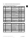
Symbol Name Function P-I Remarks
S26 Junction box paper detection
sensor
Detects the presence of paper within
the junction box.
P16-I8 P.2-7 "Fig. 2-7"
S27 Transport path-2 sensor Detects the paper transported to the
switch back Unit.
P28-I2 P.2-7 "Fig. 2-7"
S28 Transport path-3 sensor Detects the paper transported to the
switch back Unit.
P28-I2 P.2-7 "Fig. 2-7"
S29 Ejecting roller sensor Detects the rotation of the assisting
roller.
P27-I10 P.2-7 "Fig. 2-7"
S30 Stacker paper detection sen-
sor
Detects the presence/absence of the
paper in the stacker.
P27-I21 P.2-7 "Fig. 2-7"
S31 Exit sensor Detects paper exit from the EFS Unit. P24-I7 P.2-7 "Fig. 2-7"
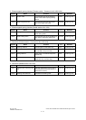
S32 Saddle tray paper detection
sensor
Detects the presence/absence of the
paper on the saddle tray.
P18-I8 P.2-7 "Fig. 2-7"
S33 Stacker home position sensor Detects the home position of the
stacker.
P20-I4 P.2-7 "Fig. 2-7"
S34 Folding motor encoder sensor Detects the rotation of the Folding
motor.
P19-I26 P.2-7 "Fig. 2-7"
S35 Folding blade home position
sensor
Detects the home position of the folding
blade.
P19-I26 P.2-7 "Fig. 2-7"
S36 Side alignment home position
sensor
Detects the home position of the side
alignment plate.
P23-I3 P.2-7 "Fig. 2-7"
S38 Paper holding home position
sensor
Detects the home position of the paper
holding unit.
P21-I20 P.2-7 "Fig. 2-7"
S39 Additional folding home posi-
tion sensor
Detects the home position of the Addi-
tional folding roller.
P24-I7 P.2-7 "Fig. 2-7"
S41 Exit transport sensor Detects the stop position of the Addi-
tional folding.
P24-I7 P.2-7 "Fig. 2-7"
S42 Additional folding motor
encoder sensor
Detects the rotation of the Additional
folding motor..
P24-I7 P.2-7 "Fig. 2-7"
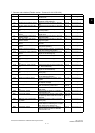
S43 Front saddle stapler home
position sensor
Detects the home position in the front
stapler for the stapling operation.
P22-I5 P.2-7 "Fig. 2-7"
S44 Rear saddle stapler home
position sensor
Detects the home position in the rear
stapler for the stapling operation
P22-I5 P.2-7 "Fig. 2-7"
S45 Front saddle staple empty
sensor
Detects the empty status of front sta-
ples in the stapler cartridge.
P22-I5 P.2-7 "Fig. 2-7"
S46 Rear saddle staple empty
sensor
Detects the empty status of rear sta-
ples in the stapler cartridge.
P22-I5 P.2-7 "Fig. 2-7"
S47 Front saddle staple top posi-
tion sensor
Detects the staple top position in the
front stapler.
P22-I5 P.2-7 "Fig. 2-7"
S48 Rear saddle staple top posi-
tion sensor
Detects the staple top position in the
rear stapler.
P22-I5 P.2-7 "Fig. 2-7"
S49 Front saddle stapler cartridge
sensor
Detects the presence/absence of the
stapler cartridge in the front stapler.
P22-I5 P.2-7 "Fig. 2-7"
S50 Rear saddle stapler cartridge
sensor
Detects the presence/absence of the
stapler cartridge in the rear stapler.
P22-I5 P.2-7 "Fig. 2-7"
SW5 Saddle unit opening/closing
switch
Cuts off drive current (24V) when it
detects that the saddle unit is opened.
P17-I10 P.2-7 "Fig. 2-7"
Symbol Name Function P-I Remarks
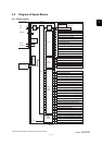
FIN Finisher control PC board
(FIN board)
Controls the Finisher P3-I37 P.2-7 "Fig. 2-7"
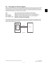
I/F Interface PC board (I/F board) Transmits signals among the punch
control PC board, finisher control PC
board and saddle control PC board.
P13-I5 P.2-7 "Fig. 2-7"
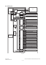
Symbol Name Function P-I Remarks
SDL Saddle control PC board
(SDL board)
Controls the Saddle Stitch Finisher. P18-I58 P.2-7 "Fig. 2-7"