


MJ-1103/1104 © 2008, 2009 TOSHIBA TEC CORPORATION All rights reserved
DISASSEMBLY AND INSTALLATION
4 - 86
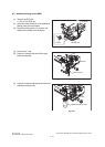
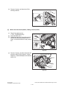
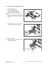
[H] Transport path switching solenoid (SOL5) (MJ-1104)
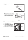
(9) Remove 2 screws, and then take off the gate
solenoid.
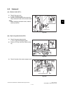
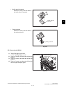
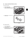
Note:
When installing the gate solenoid, install the
bracket with 2 screws as shown in the figure,
and then fix it at the position where the gap
between the gate flap and the shaft of the
entrance roller falls within 0.4 to 0.8 mm.
Fig. 4-242
Fig. 4-243
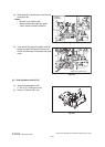
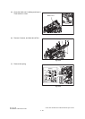
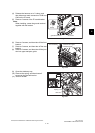
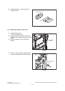
(1) Take off the right upper cover.
P.4-7 "[J] Right upper cover"
(2) Take off the relay guide, feeding discharge
brush and right cover.
P.4-7 "[K] Relay guide / Feeding dis-
charge brush / Right cover"
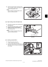
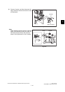
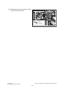
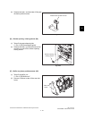
(3) Remove 4 screws of the FIN board bracket.
Fig. 4-244
Gate solenoid
0.4mm to 0.8mm
A
A
B
B
Bracket
Gate flap
Shaft of the entrance roller
FIN board
bracket